Striate-body fixation fixture, wire-harness protector and fixation clip

Inactive Publication Date: 2005-11-24
YAZAKI CORP
View PDF4 Cites 14 Cited by
  • Summary
  • Abstract
  • Description
  • Claims
  • Application Information

AI Technical Summary

Benefits of technology

[0013] The positioning plate includes a curved wall recessed from the first side of the base plate. The curved wal

Problems solved by technology

The fixation plate, however, is an element having insertion holes formed for passage of a band clamp merely, and it i

Method used


Image

  • Striate-body fixation fixture, wire-harness protector and fixation clip
  • Striate-body fixation fixture, wire-harness protector and fixation clip
  • Striate-body fixation fixture, wire-harness protector and fixation clip

Examples


Example

[0023] Referring to accompanying drawings, an embodiment of the invention will be described below.

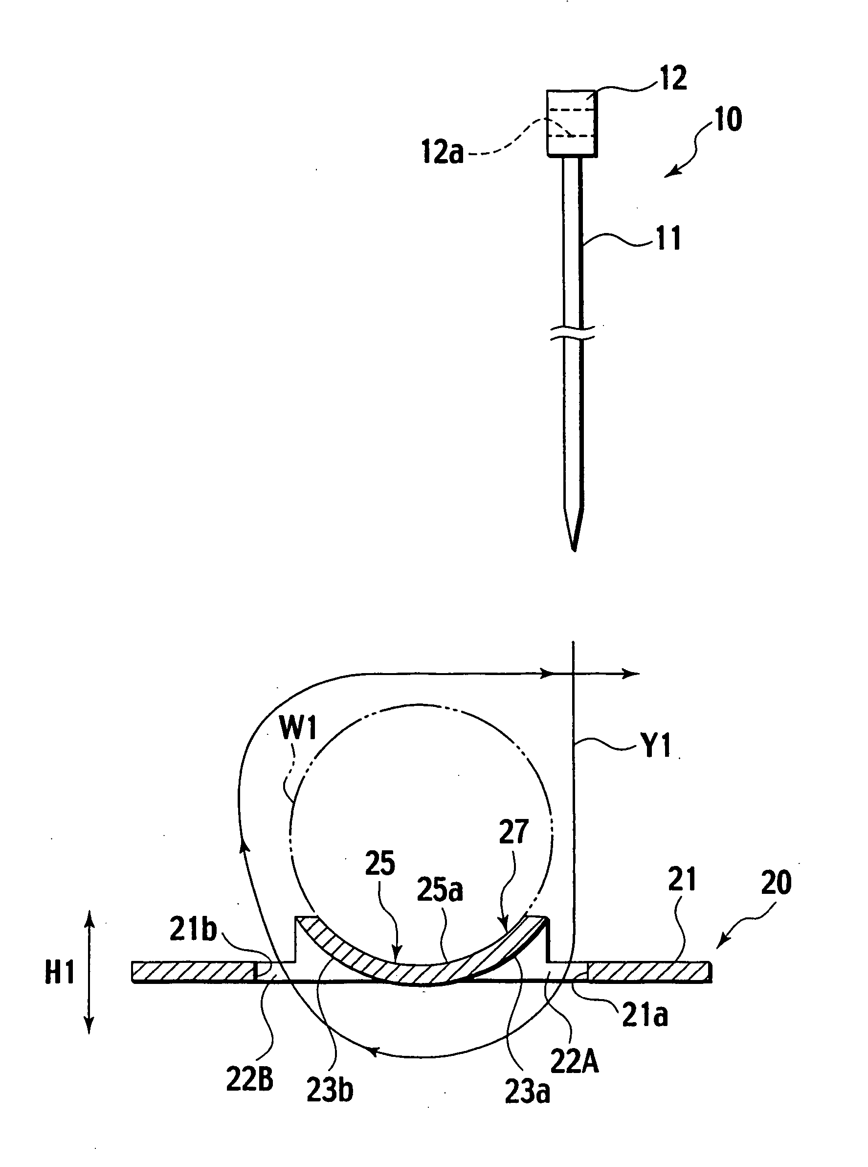
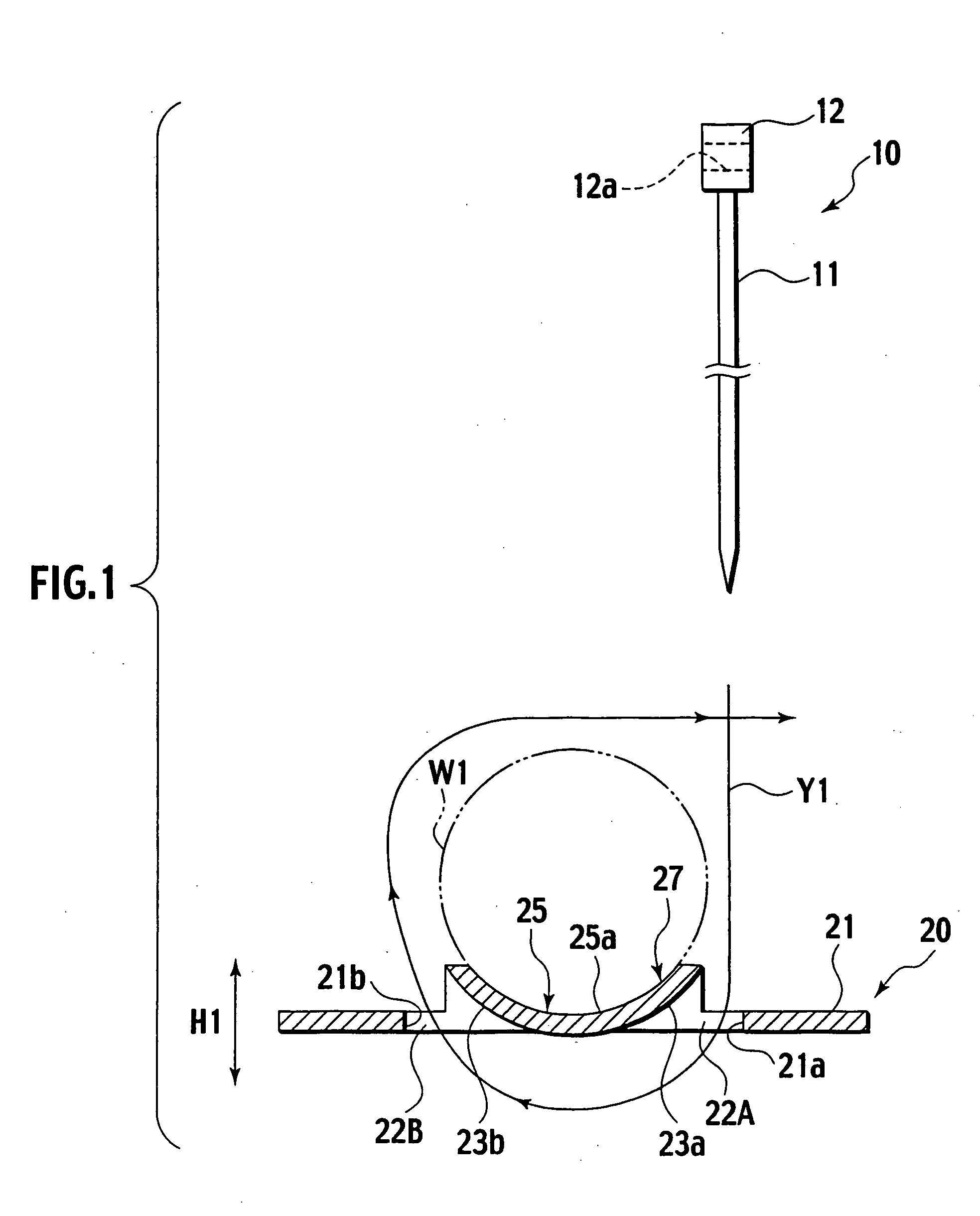
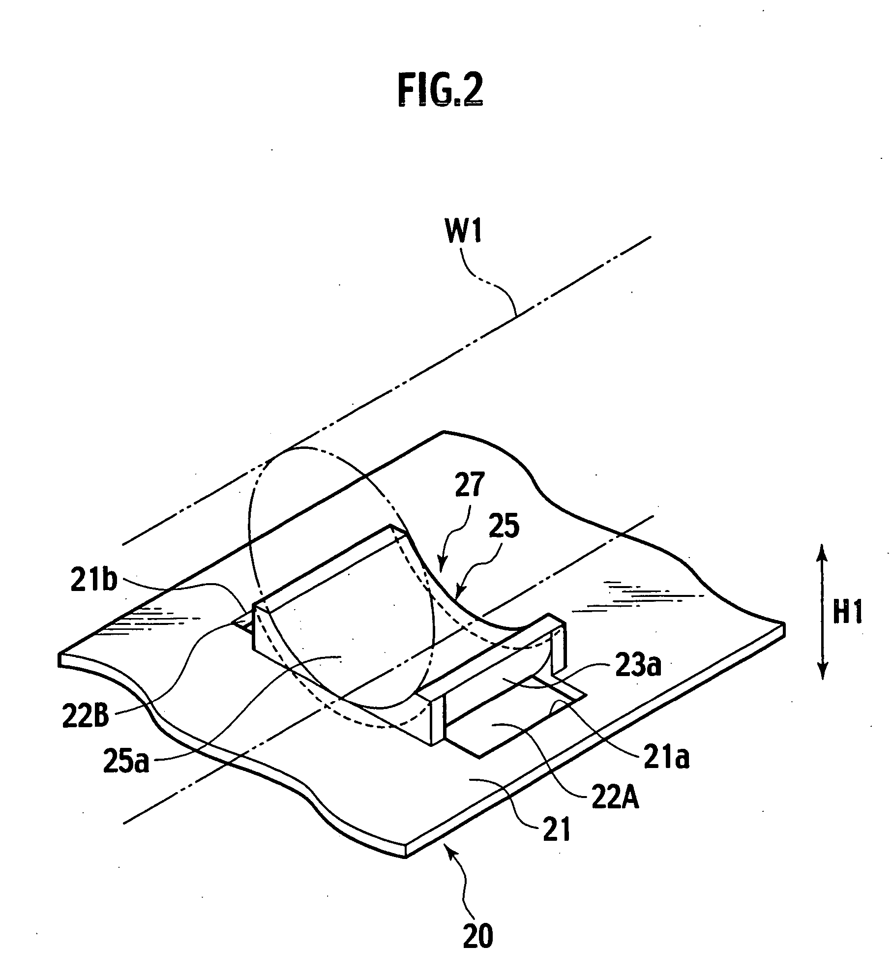
[0024] In FIGS. 1 and 2, a fixation plate 20 of the embodiment is applied to one protective wall of a wire-harness protector.

[0025] This fixation plate 20 has first and second sides opposite to each other in a thickness direction H1 thereof. The fixation plate 20 includes a level part 21 as a base plate. The fixation plate 20 includes a positioning part 27 as a positioning plate arranged inside the level part 21 to mount a wire harness (striate body) W1 thereon on the first side. The positioning part 27 has, on both sides thereof, two rectangular first and second insertion holes 22A, 22B through the level part 21 in a thickness direction H1 of the fixation plate 20. The first and second insertion holes 22A, 22B are separated from each other in a transverse direction of the wire harness W1. Additionally, the first and second insertion holes 22A, 22B have, outside thereof, outer sidewal...


PUM


Abstract

A striate-body fixation fixture includes a base plate a first side and a second side opposite to each other. The fixture includes a positioning plate included in the base plate for mounting the striate body in position on the first side of the base plate. The fixture includes first and second insertion holes extending through the base plate and opposed to each other with respect to the positioning plate. The fixture includes a guide wall defining at least one of the first and second insertion holes and approaching the other insertion hole for guiding a band to secure the striate body on the fixture as the guide wall extends toward the second side of the base plate.

Description

CROSS-REFERENCE TO RELATED APPLICATIONS [0001] This application is based upon and claims the benefit of priority from Japanese Patent Application No. 2004-140820 filed on May 11, 2004; the entire contents of which are incorporated herein by reference. BACKGROUND OF THE INVENTION [0002] The invention relates to a striate-body fixation fixture for mainly securing a striate-body, such as wire harness, by use of a band clamp, a wire-harness protector having the fixation plate and a wire-harness fixation clip. [0003] In general, when it is required to fix a wire harness to any member of a vehicle, a band clamp (otherwise known as “binding band”) is employed as such fixation means (e.g. Japanese Patent Application Laid-open No. 2000-253536). [0004] For example, in order to fix a wire harness to a fixation plate for a wire-harness protector by use of a band clamp, there are proposed a variety of methods. Note, the fixation plate is provided with two insertion holes. In one method, it is fi...

Claims


Application Information

Patent Timeline
IPC IPC(8): F16B2/08A61F2/30F16L3/04F16L3/10F16L3/137H02G3/30
CPCF16L3/04F16L3/1058Y10T24/10H02G3/30F16L3/137
Inventor TSUCHIYA, HIROKAZU
Owner YAZAKI CORP
Why Eureka
Try Eureka