Desiccant-assisted air conditioning system and process

a technology of desiccant and air conditioning system, applied in the field of desiccant-assisted air conditioning system and process, can solve the problems of airborne contaminants, insufficient delivery of air conditions, ineffective humidity control of most conventional air conditioning process and system, etc., and achieve the effect of facilitating the desiccant sorption and desorption process

Inactive Publication Date: 2005-11-24
ALLANCO TECH
View PDF2 Cites 52 Cited by
  • Summary
  • Abstract
  • Description
  • Claims
  • Application Information

AI Technical Summary

Benefits of technology

[0015] The present invention overcomes the aforementioned problems and is distinguished over the prior art in general, and these patents in particular, by a desiccant-assisted air conditioning system and process which utilizes a compressor, a condenser coil, an evaporator coil, supplemental desiccant coils, and damper and valve arrangements that direct air and refrigerant through the system coils in several different thermodynamic operating paths and cycles for significantly improved operating efficiency, energy conservation, and conditioned air output. The system effectively combines, transfers and reverses thermodynamic energies between the desiccant, the refrigerant and the crossing air, and maximizes the refrigerant vapor compression closed cycle and desiccant vapor compression open cycle.
[0016] The present invention utilizes the conventional condenser and evaporator coils in combination with a pair of desiccant coils to increase total coil average temperature and refrigerant energy transfer capacity to the desiccant in regeneration. The system not only utilizes the desiccant coils to exchange energy externally in the crossing air gas phase, but also utilizes the desiccant coil properties to augment the refrigerant absorption and rejection energies, and utilizes the properties of the refrigerant to exchange internal heat energy with the desiccant coils to condition the desiccant more efficiently.
[0017] The normally rejected refrigerant energy is transferred from the conventional condenser coil to the first desiccant coil, thereby increasing its refrigeration pressure and temperature capacity. The concentrated refrigerant energy and increased capacity dissipates the concentrated heat through the desiccant material, thereby increasing the vapor-pressure differential of the desiccant in relation to its crossing air stream and vapor pressure conditions. The increased refrigerant energy regenerates the desiccant material to a dryer condition prior to the switching to a cross flow mode of operation. In this process, the adiabatic cooling effect of the second desiccant coil provided by the evaporation of the water content in its desiccant material to the passing air stream is not adversely affected because of the transferred increased concentrated refrigerant energy and capacity, which is transferred gradually. The sorption process and adiabatic heating effect of the second desiccant coil provides normally rejected work energy which is used in series with the refrigerant compressor to serve as a co-generator in the refrigeration cycle, and also provides simultaneous rapid cooling of the desiccant, accelerates dehumidification of its air stream with no appreciable sensible heat added to the air stream, and allows the accumulation of moisture prior to switching from a straight airflow mode to a cross airflow mode.
[0019] In the cross flow mode and desiccant switching cycle, when the second coil has a diminished capacity to attract moisture and after the first has sufficiently dried, the air and refrigerant paths are switched between the desiccant coils and the previously moistened second coil becomes the desiccant regeneration coil and the dried first coil becomes the process desiccant coil. Thus, their roles are reversed, and the states of their previous moisture conditions facilitates the desiccant sorption and de-sorption process.

Problems solved by technology

Airborne contaminants are also often carried with the moisture in the supplied air streams.
Most conventional air conditioning processes and systems do not effectively control humidity, nor provide adequate delivery air conditions, in anticipation of the various changes and demands of the indoor or outdoor environments.
Although conventional systems provide dehumidification, it is an uncontrolled byproduct of its evaporator coil cooling process, and results in the inadequate control of humidity, and excessive energy consumption, and can also result in building and or space content damage.
The temperature of the water on the fins tends to become lower quickly, because of its direct conductive energy exchange, and at lower temperatures it consequently crystallizes and freezes; it becomes an insulator and diminishes energy transfer capabilities and effectiveness.
The ice build can also restrict the air path and further diminish the conductive thermal energy transfer capabilities and efficiencies of the refrigerant.
Thus, if frost becomes a problem, the system requires sequencing to a defrost mode, which stops the refrigeration cooling effects.
Defrosting or non-continuous cooling can adversely affect the air quality and / or comfort level in the conditioned space.
However, the transferable energy provided by the desiccant upon switching is far from being maximized.
The total coil average temperature and the average regeneration refrigerant energy transferred to the desiccant is definitely not maximized and the pre-dried desiccant condition elevates very little in proportion to the total average refrigerant conditions and results in a less effective refrigerant adiabatic cooling effect in the refrigeration cycle to augment the compressor efficiency.
In the coil switching process, the inefficient total coil average temperature can produce a situation where the regenerated desiccant has insufficient dryness and acts as a heat sink in the process air stream, which results in re-heating the crossing process air and wasted heat energy.
A system with only two desiccant coils that replace the conventional evaporator and condenser is also disadvantageous in that it does not provide steady constant air delivery conditions when switching the coils.
As with most desiccant wheel systems, this process has limitations in effective cooling.
This causes an increase in the water content of the desiccant.

Method used


Image

  • Desiccant-assisted air conditioning system and process
  • Desiccant-assisted air conditioning system and process
  • Desiccant-assisted air conditioning system and process

Examples


Embodiment Construction

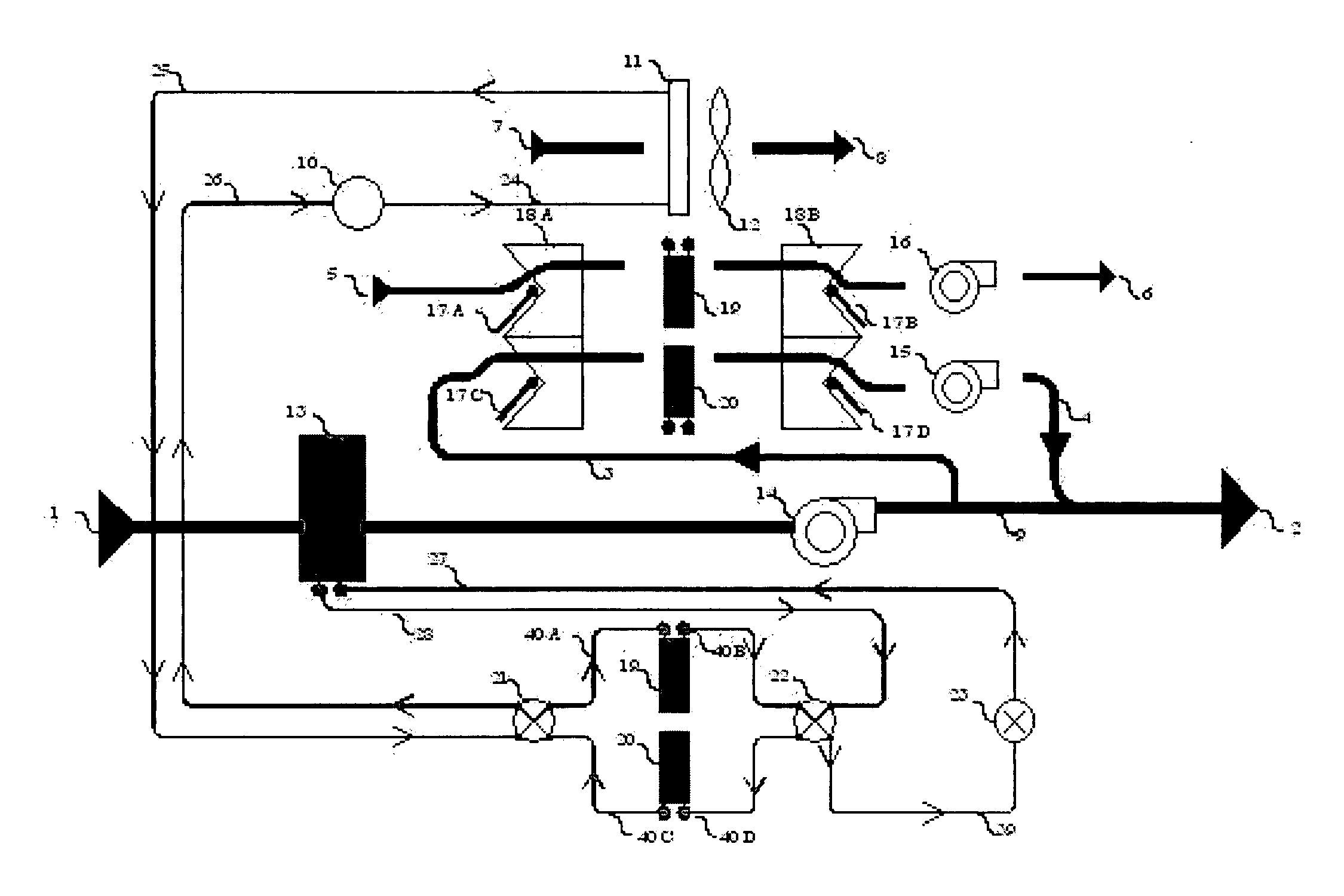
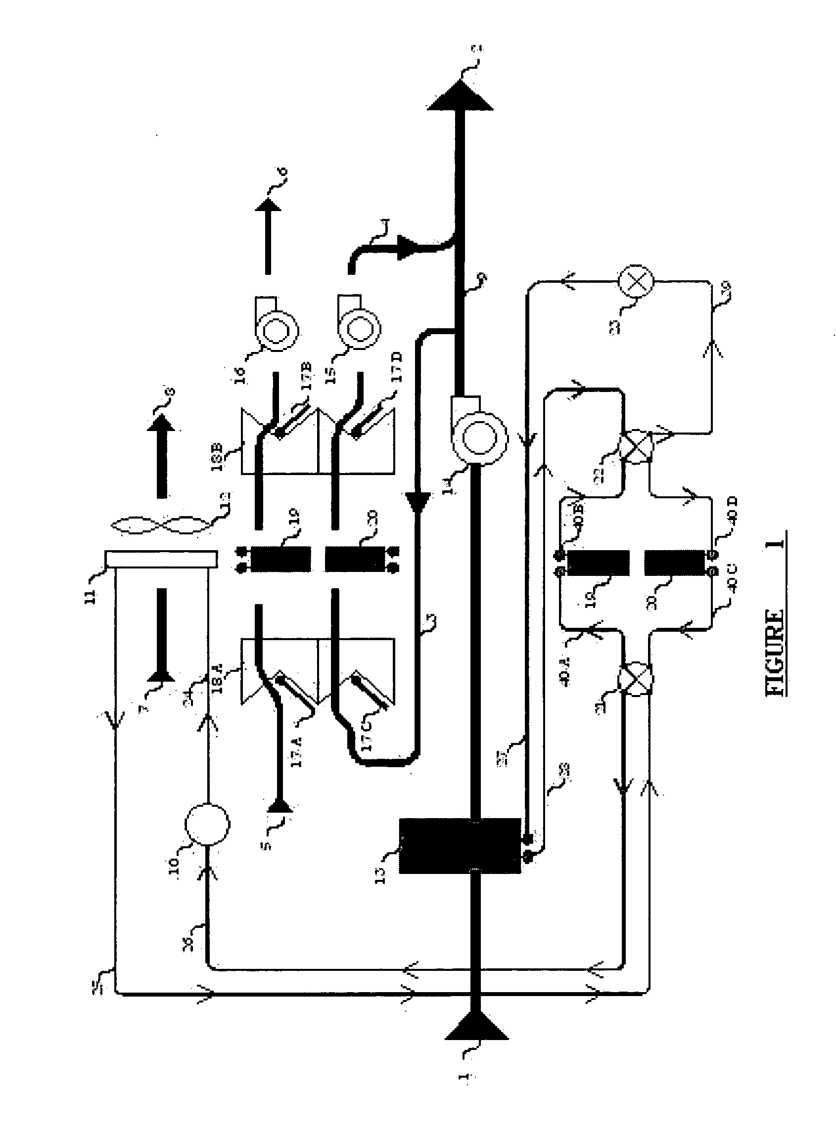
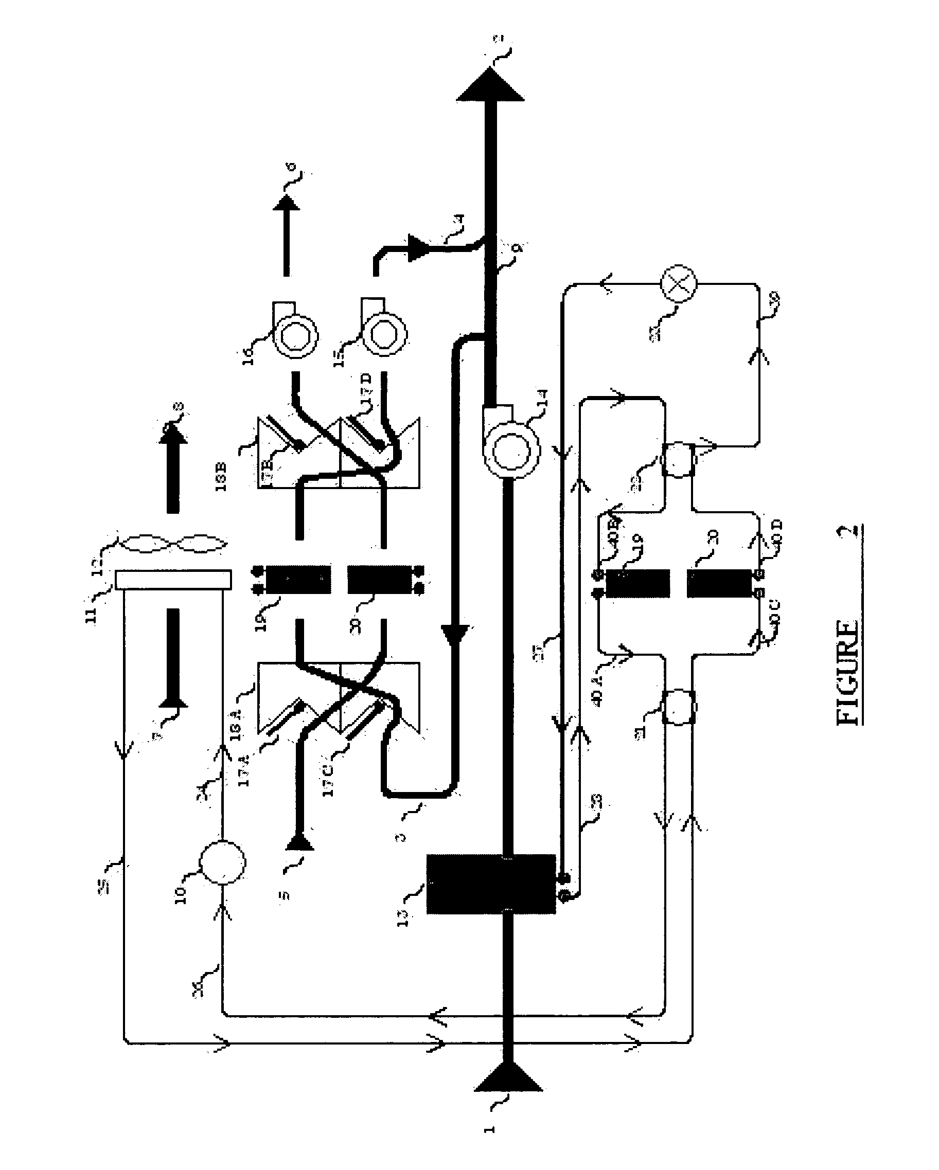
[0036] As used herein, the term “air conditioning” is a general term and includes dehumidified air, humidified air, and cool or warm air, or a combination thereof. The term “process air” means any air that is to be processed by the present system. The term “regeneration air” means any air that is used to regenerate the desiccant material. The term “supply air” means the air that is supplied to a spaced to be provided with conditioned air. The term “return air” means the air either returning from the conditioned space or newly introduced air. The term “refrigerant” means a substance used as an agent for cooling or heating, and includes such substances in a liquid, gas, or vapor form. The term “desiccant” means a drying substance or agent and may include materials such as silicas, aluminas, titanium, lithium chloride, zeolites, polymers and clay. The term “compressor” means a machine for reducing the volume and increasing the pressure of gases in order to condense and expand the gases...


PUM


Abstract

A desiccant-assisted air conditioning system utilizes a compressor (10), a condenser coil (11), an evaporator coil (13), supplemental desiccant coils (19, 20) connected therewith, and damper (18A, 19B) and valve arrangements that direct air and refrigerant through the system coils in several different thermodynamic operating paths. The system combines, transfers and reverses thermodynamic energies between the desiccant, the refrigerant and the crossing air, and simultaneously maximizes the refrigerant vapor compression closed cycle and desiccant vapor compression open cycle. The desiccant coils (19, 20) not only provide an effective gas phase change in their crossing air streams, but also simultaneously provide endothermic and exothermic energy exchanges between the air streams and the passing refrigerant that maximize the operating efficiency of the compressor, condenser coil, and evaporator coil, conserves energy, and produces quality conditioned air output.

Description

CROSS REFERENCE TO RELATED APPLICATIONS [0001] This application claims priority of U.S. Provisional Application Ser. No. 60 / 573,086, filed May 22, 2004, U.S. Provisional Application Ser. No. 60 / 588,409, filed Jul. 16, 2004, and U.S. Provisional Application Ser. No. 60 / 592,879, filed Jul. 30, 2004.BACKGROUND OF THE INVENTION [0002] 1. Field of the Invention [0003] This invention relates generally to desiccant-assisted air conditioning systems and processes, and more particularly to an air conditioning system utilizing a compressor, a condenser coil, an evaporator coil, supplemental desiccant coils, and damper and valve arrangements that direct air and refrigerant through the system in several different thermodynamic operating paths and cycles for significantly improved efficiency and energy conservation. [0004] 2. Background Art [0005] The control of humidity in indoor environments plays a very important role in providing indoor air quality. Reducing the volume of moisture indoors ca...

Claims


Application Information

Patent Timeline
Patent Type & Authority Applications(United States)
IPC IPC(8): F24F3/14F25B13/00F25D23/00
CPCF24F3/1411F24F3/1429F25B13/00
Inventor LANDRY, GERALD
Owner ALLANCO TECH
Why Eureka
Try Eureka