Electrical energy disconnection device

a technology of electrical energy and disconnection device, which is applied in the direction of coupling device connection, contact mechanism, inductance, etc., can solve the problems of inability to distinguish the primary winding from the secondary winding, high cost, and inability to solve the problem of high-voltage applications

Inactive Publication Date: 2005-11-24
ALSTOM TECH LTD
View PDF12 Cites 6 Cited by
  • Summary
  • Abstract
  • Description
  • Claims
  • Application Information

AI Technical Summary

Benefits of technology

[0030] The fixing fitting may be provided internally with a pivotally mounted bushing, thereby enabling

Problems solved by technology

That solution is expensive because not all of the characteristics of the disconnector are used.
In the figure, it is not possible to distinguish the primary winding from the secondary winding.
The drawback with that configuration is that it is not reliable for high-voltage applicatio

Method used


Image

  • Electrical energy disconnection device
  • Electrical energy disconnection device
  • Electrical energy disconnection device

Examples


Embodiment Construction

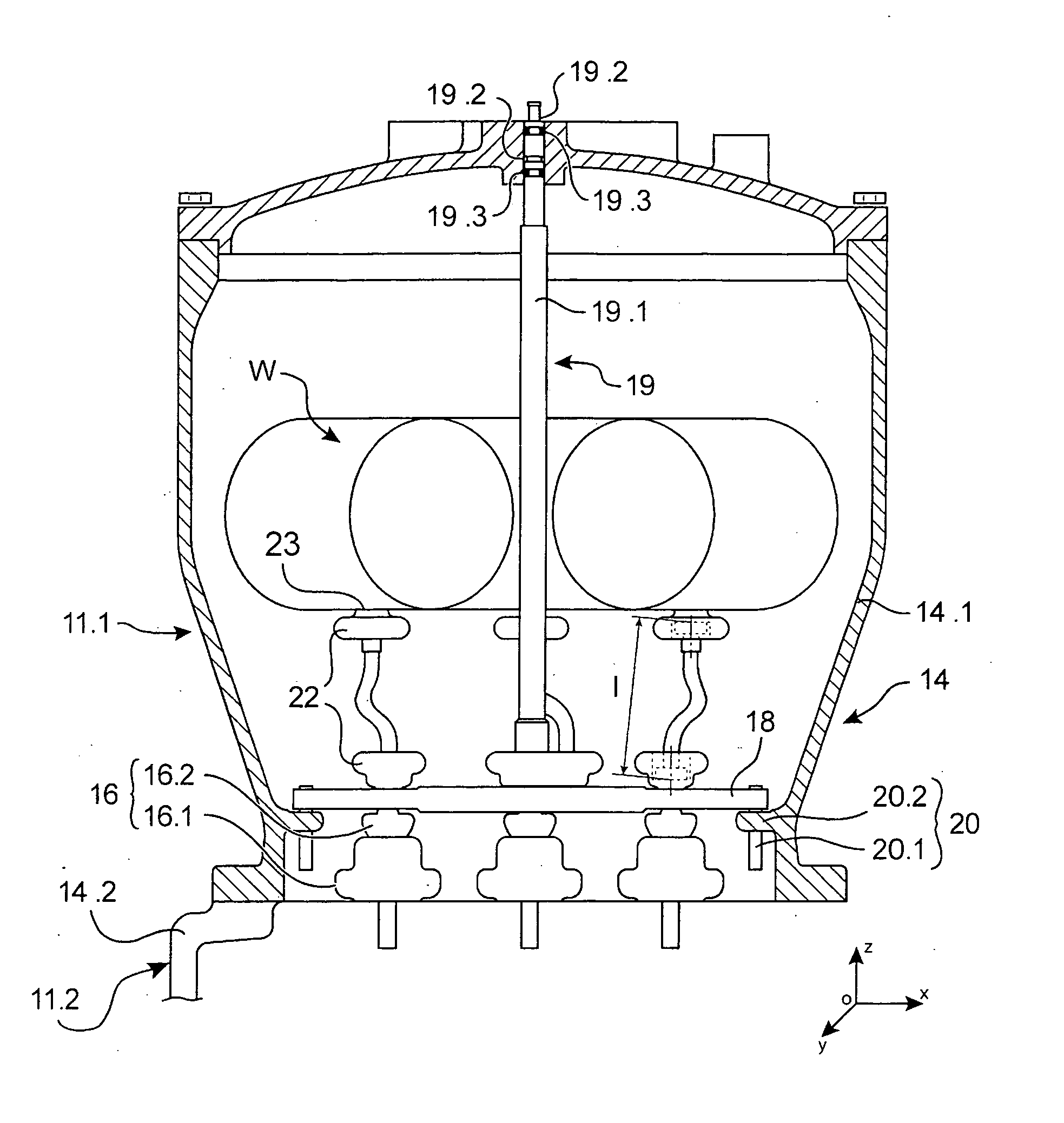
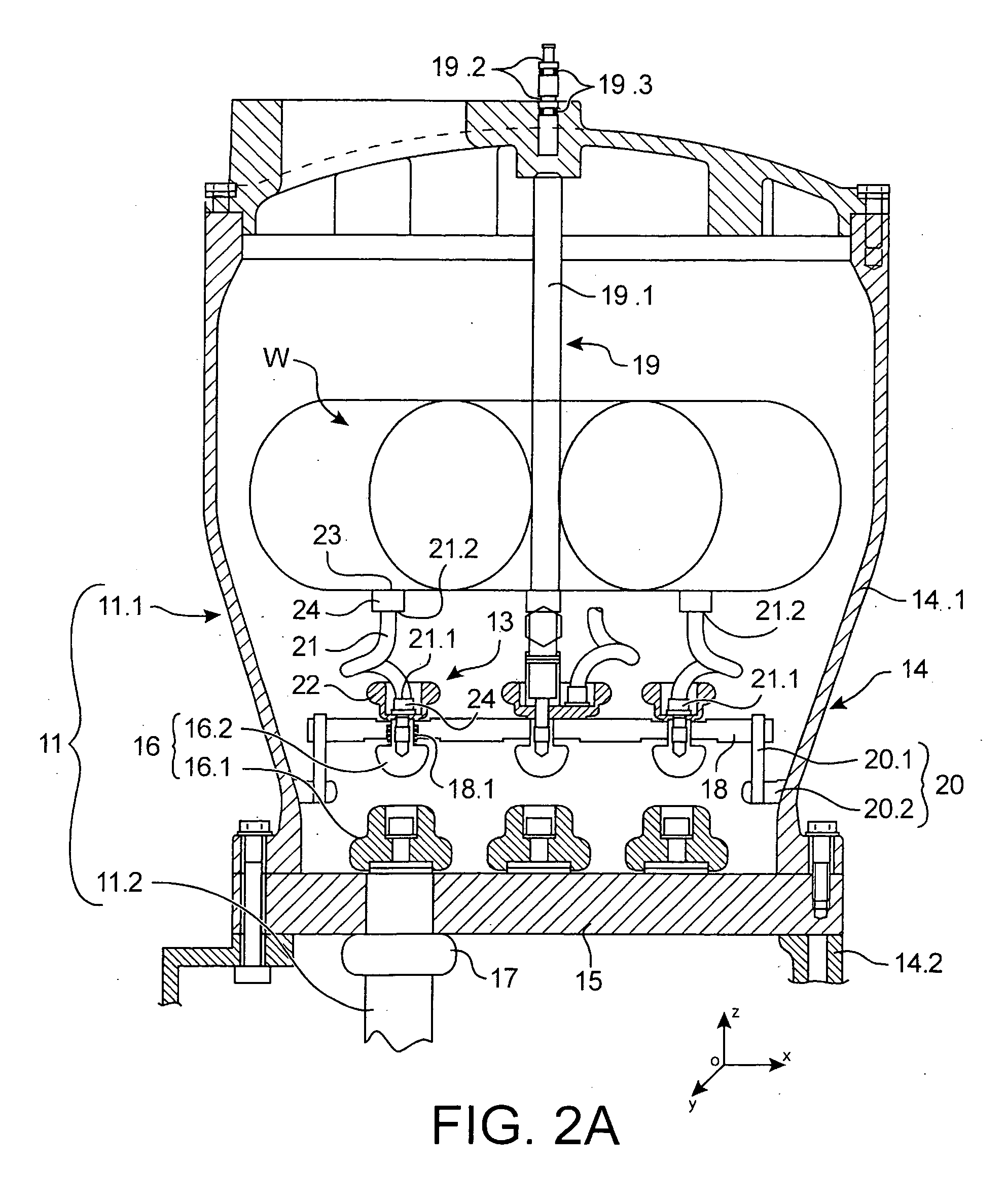
[0046] Reference is made to FIGS. 2A and 2B which show a first embodiment of a disconnection device of the invention, respectively in an open state and in a closed state. The disconnection device is designed to separate a first portion 11.1 of a high-voltage electrical circuit 11 electrically from a second portion 11.2 thereof.

[0047] In this example, the first portion 11.1 of the electrical circuit is represented diagrammatically by a voltage transformer. The electrical circuit 11 is a portion of a high-voltage gas-insulated electricity substation. The second portion 11.2 of the electrical circuit 11 is connected to the rest of the electricity substation by a conductor represented diagrammatically by a cylindrical busbar.

[0048] Other applications for the disconnection device of the invention are naturally possible.

[0049] The electrical circuit 11 is placed in a gastight enclosure 14 designed to be filled with an insulating gas, e.g. sulfur hexafluoride SF6.

[0050] The transformer...


PUM


Abstract

The invention relates to disconnection device designed to separate a first portion (11.1) of an electrical circuit (11) electrically from a second portion (11.2) of said circuit, the disconnection device comprising:
    • at least one pair of contacts (16), one of which contacts (16.2) is a moving contact, the pair of contacts having an open state and a closed state; and
    • a flexible conductor (21) fixed at one end to the moving contact (16.2) and serving to be fixed at the other end to one of the portions (11.1) of the electrical circuit. The conductor comprises a flexible tube (21) that is electrically conductive, at least at its surface, and that has bending stiffness that is low enough to enable it to bend without kinking, and torsion stiffness that is high enough to enable it to take up a shape and a position that are substantially reproducible at least in the closed state. Application in particular to gas-insulated high-voltage electricity substations.

Description

TECHNICAL FIELD [0001] The invention relates to an electrical energy disconnection device. The term “electrical disconnection device” is used to cover a disconnector, a circuit-breaker, a grounding device, or a switch. [0002] The invention relates more particularly to a simplified high-voltage disconnector which is capable of separating and / or of interconnecting two portions of high-voltage circuit that have a low working current (e.g. less than 1 amp). Such an item of switchgear operates turned-off. It is recalled that a disconnector is a device designed to isolate a portion of an electrical circuit from the rest of the circuit, it being desired to take said portion out of operation or to work on it or to take measurements on it without danger. Such a disconnector can be used, in particular for electrically isolating a voltage transformer included in a gas-insulated substation (GIS) from the rest of the substation. When testing the value of the voltage, it can be desired to separat...

Claims


Application Information

Patent Timeline
IPC IPC(8): H01F38/26H01H1/58H01H3/00H01H33/02H01H33/66H02B13/025
CPCH01H1/5822H01F38/26H02B13/0356H01H33/42H01H33/00
Inventor ANDERMATT, ERNSTDOESSEGGER, ANDREPOHLINK, KARSTEN
Owner ALSTOM TECH LTD
Why Eureka
Try Eureka