Water sprayer

Inactive Publication Date: 2005-11-24
HSIN YUIRS INDAL
View PDF7 Cites 45 Cited by
  • Summary
  • Abstract
  • Description
  • Claims
  • Application Information

AI Technical Summary

Benefits of technology

[0011] It is the primary objective of the present invention to provide a wat

Problems solved by technology

This pattern changing procedure is not easy to perform.
The water sprayer may become

Method used


Image

  • Water sprayer
  • Water sprayer
  • Water sprayer

Examples


Embodiment Construction

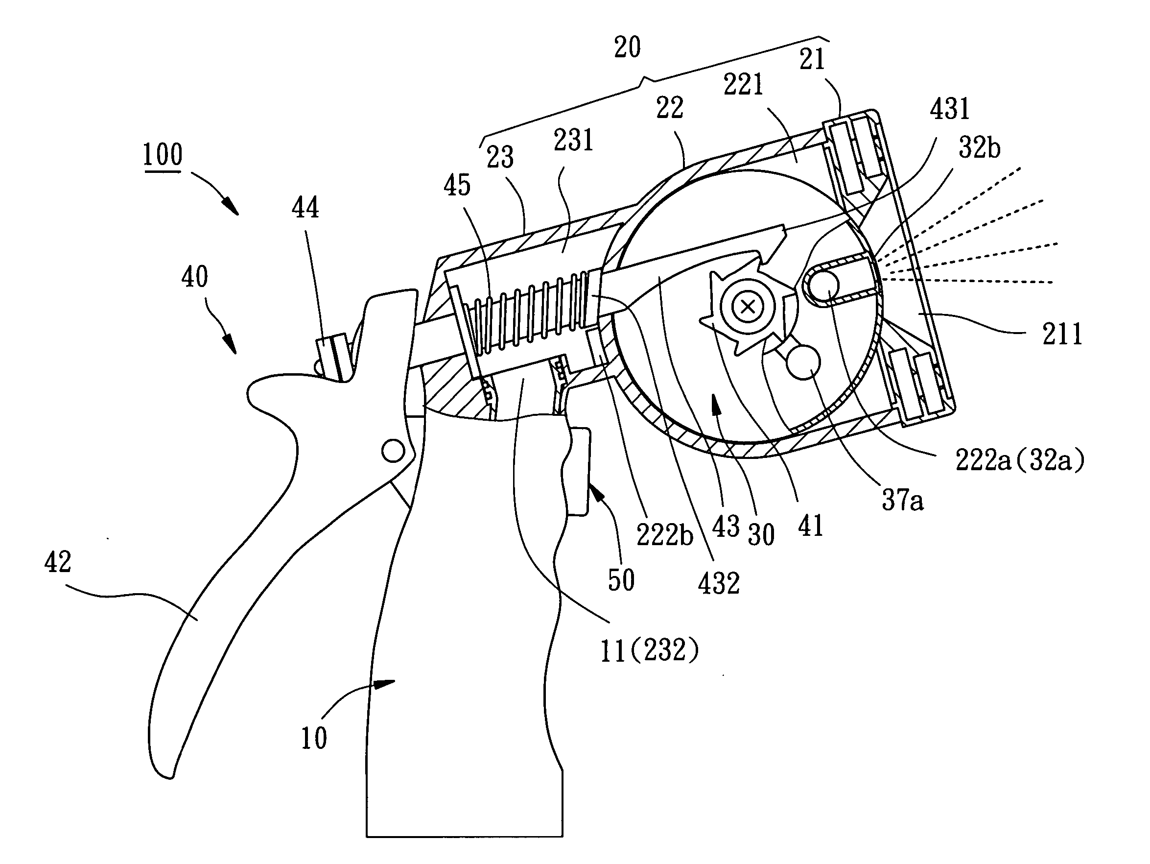
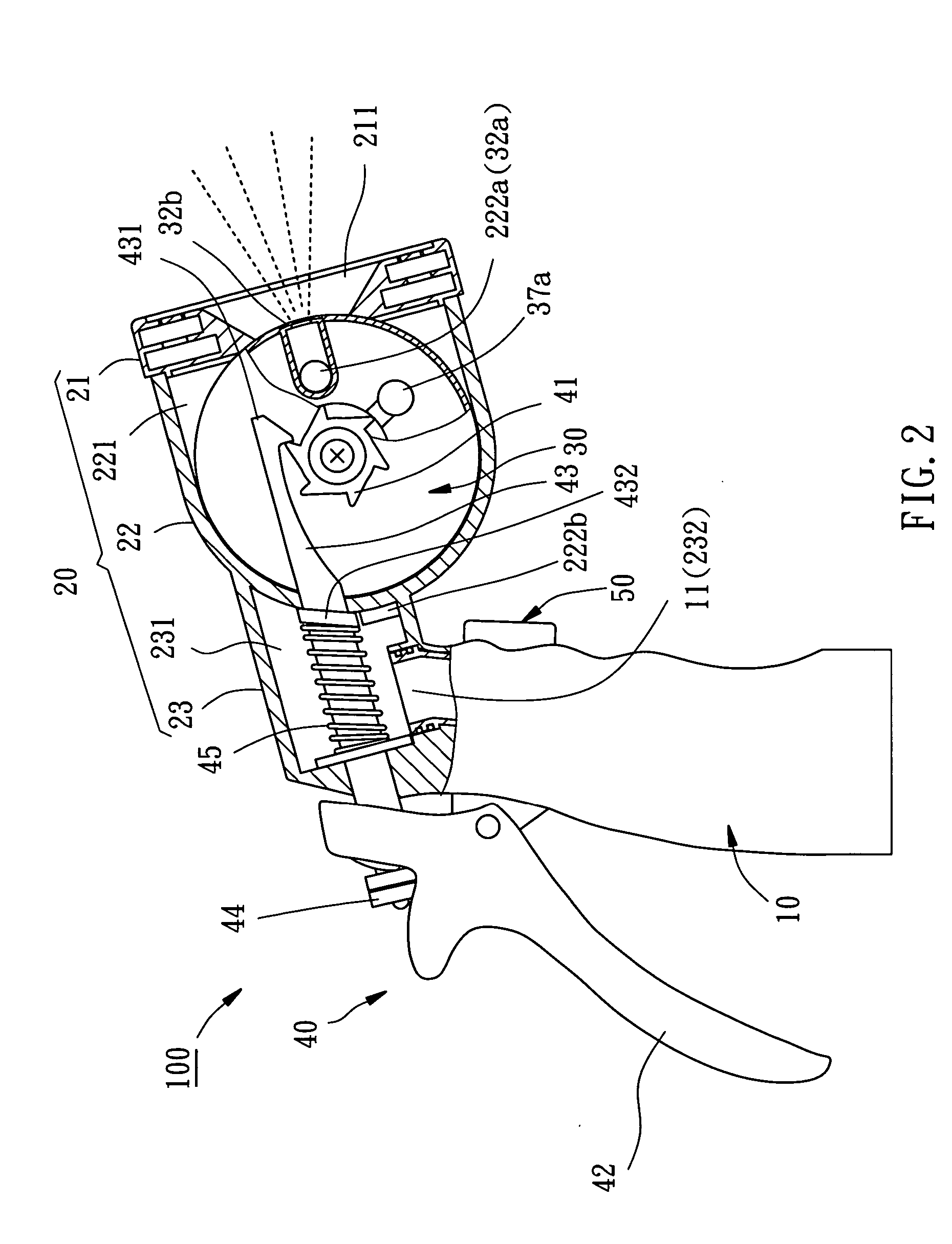
[0031] Referring to FIGS. 2-4, a water sprayer 100 in accordance with the preferred embodiment of the present invention is shown comprised of a housing 10, a water wheel holder 20, a water wheel 30, a control unit 40, and a switch 50.

[0032] The housing 10 is made for the holding of the hand, comprising a water inlet 11 connectable to an external water source.

[0033] The water wheel holder 20 comprises a head 21 at the front side, a rear extension 23 at the rear side, and a body 22 connected between the head 21 and the rear extension 23. The body 22 defines therein a receiving chamber 221. The rear extension 23 has a water chamber 231, and a mounting through hole 232 extended across the water chamber 231. By means of the mounting through hole 232, the water wheel holder 20 is fastened to the housing 10, keeping the water chamber 231 in fluid communication with the water inlet 11.

[0034] Referring to FIGS. 5-7 and FIGS. 2-4 again, the head 21 comprises a first water outlet 211 in com...


PUM


Abstract

A water sprayer includes a housing and a water wheel holder connected to the housing. The water wheel holder has a receiving chamber therein in communication with a water inlet in the housing, a first water outlet, and a second water outlet formed of a plurality of fine holes. A water wheel is rotatably stepwise mounted in the water wheel holder and located inside the receiving chamber. The water wheel has a plurality of primary water passages, which are selectively connectable between the water inlet and the first water outlet for guiding water from the water inlet to the first water outlet, and a secondary water passage, which is selectively connectable between the water inlet and the second water outlet for guiding water from the water inlet to the second water outlet.

Description

BACKGROUND OF THE INVENTION [0001] 1. Field of the Invention [0002] The present invention relates watering apparatus for gardening and more particularly, to a water sprayer that can easily be controlled to change the spray pattern of water. [0003] 2. Description of the Related Art [0004]FIG. 1 shows a water sprayer according to the prior art. According to this design, the water sprayer 1 (the so-called pistol nozzle) comprises a housing 2, a control lever 3, and a spray-pattern dial assembly 4. The housing 2 comprises a handle 2a, which defines therein a water passage (not shown) connectable to water source, and a dial mount 2b. The dial mount 2b comprises a water outlet 2d in communication with the water passage in the handle 2a, and a screw hole 2c. The control lever 3 is pivoted to the housing 2 and adapted to control supply of water to the water passage in the dial mount 2b. The spray-pattern dial assembly 4 is comprised of a base 4a and a dial 4b. The base 4a is affixed to the ...

Claims


Application Information

Patent Timeline
IPC IPC(8): B05B1/16B05B1/18
CPCB05B1/1636B05B1/18B05B1/1645B05B12/002
Inventor WANG, KUAN-HSIUNG
Owner HSIN YUIRS INDAL
Why Eureka
Try Eureka