Drip irrigation hose and method for making same

Inactive Publication Date: 2005-11-24
COHEN
View PDF4 Cites 54 Cited by
  • Summary
  • Abstract
  • Description
  • Claims
  • Application Information

AI Technical Summary

Benefits of technology

[0017] Such a construction enables water wastage due to leakage to be substantially reduced, particularly where the irrigation system is intermittently operated for relatively short periods, rather than co

Problems solved by technology

Drip irrigation hoses are increasingly being used for irrigating various types of plants since they supply the water directly to the root regions of the plants, and therefore are highly conservative of water resources.
One problem in using drip irrigation hoses is the difficulty in ensuring relatively uniform discharge rates along the length of the hose.
This problem is particularly acute where extremely long lengths of the hose are used since the hose itself produces a pressure drop along its length tending to decrease the discharge rate of the emitters at the end of the hose.
This sensitivity of the discharge rate to the water pressure is also a problem where the land being irrigated is not flat and even.
Another problem with such drip irrigation hoses is sensitivit

Method used


Image

  • Drip irrigation hose and method for making same
  • Drip irrigation hose and method for making same
  • Drip irrigation hose and method for making same

Examples


Embodiment Construction

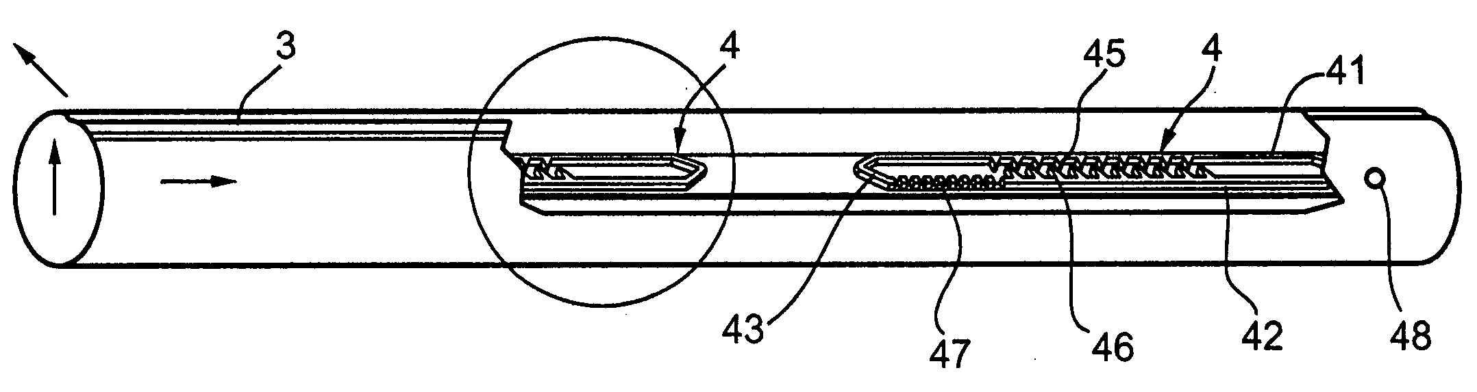
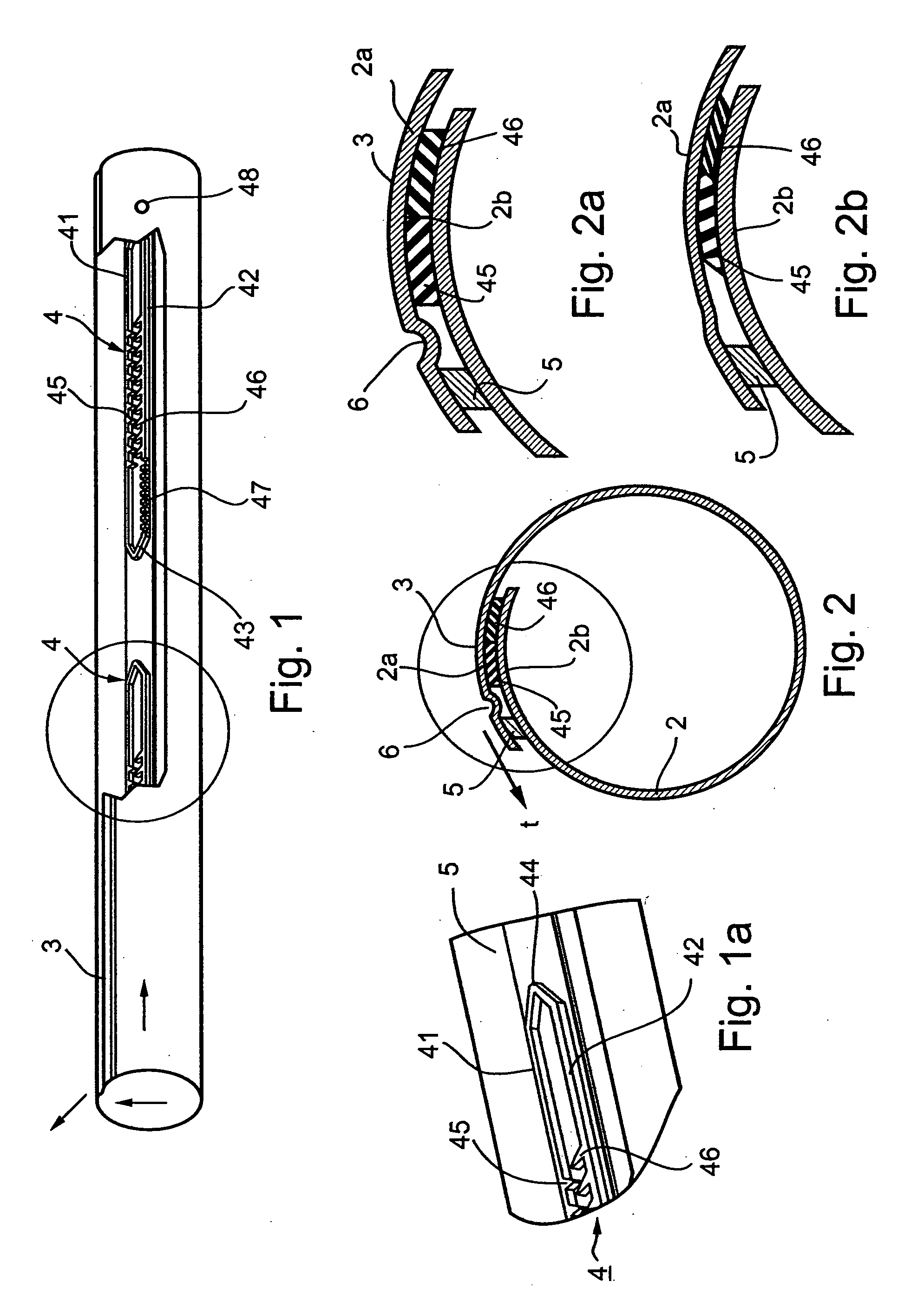
[0059] As indicated earlier, FIGS. 1 and 2 illustrate a drip irrigation hose corresponding to the constructions illustrated in FIGS. 1 and 2 of the above-cited U.S. Pat. No. 6,371,390.

[0060] Briefly, the drip irrigation hose illustrated in FIGS. 1 and 2 comprises a sheet 2 of a thin, flexible plastic material having opposed outer edge portions 2a, 2b which are overlapped and bonded together to form a seam 3 extending longitudinally of the so-produced tube for conducting pressurized water therethrough. A plurality of emitter elements, each generally designated 4, are bonded to and between the overlapping portions 2a, 2b of the sheet 2 at longitudinally-spaced locations along the seam 3, and define a plurality of restricted flow passageways for discharging water from outlets 48 in the seamed hose at a slow rate.

[0061] The overlapping portions 2a, 2b of the flexible sheet are bonded together both by the emitter elements 4, and by a continuous, longitudinally-extending rib 5 extending...


PUM


Abstract

A drip irrigation hose includes a plurality of emitter elements secured to a tube at longitudinally-spaced locations to define, with an inner surface of the tube, a plurality of labyrinths each having an inlet in communication with the interior of the tube, and an outlet in communication with a tube outlet for discharging water from the tube outlet at a slow rate. The labyrinths are defined by a continuous strip of a relatively inelastic material bonded to the inner surface of the tube, and a formation of a relatively elastic material shaped to define at least the tips of a group of teeth for each of the emitter elements producing, with the inner surface of the tube a turbulent flow passageway at each of the longitudinally spaced locations along the length of the tube. In some embodiments the drip irrigation hose is formed with a clearance between the inner surface of the tube and the teeth normally bypassing at least a part of each labyrinth in the non-pressurized condition of the tube, which clearance is closed in the pressurized condition of the tube to render the labyrinths effective to regulate the flow therethrough in response to pressure.

Description

RELATED APPLICATIONS [0001] The present application is a continuation-in-part of International Patent Application PCT / IL02 / 00953, filed Nov. 26, 2002, which application claims priority from U.S. Provisional Patent Application No. 60 / 332,568 filed Nov. 26, 2001 which application includes subject matter of U.S. application Ser. No. 10 / 197,433 of Jul. 18, 2002, which application is a continuation-in-part of U.S. application Ser. No. 09 / 639,768 filed Aug. 21, 2000, now U.S. Pat. No. 6,371,390. The contents of the above International Publication and U.S. patent are incorporated herein by reference.FIELD AND BACKGROUND OF THE INVENTION [0002] The present invention relates to drip irrigation hoses and to methods for making such hoses. [0003] Drip irrigation hoses are increasingly being used for irrigating various types of plants since they supply the water directly to the root regions of the plants, and therefore are highly conservative of water resources. One type of irrigation hose is co...

Claims


Application Information

Patent Timeline
IPC IPC(8): A01G25/02B05B15/00
CPCA01G25/026A01G25/023Y02A40/22
Inventor COHEN, AMIR
Owner COHEN
Why Eureka
Try Eureka