Safety shield for an ice shaving machine

a safety shield and ice shaving technology, which is applied in the direction of threshers, manufacturing tools, lighting and heating apparatus, etc., can solve the problems of not being completely reliable, the blade and other blade components could do serious damage to the hands of the user of the machine, and the unit could not be completely reliabl

Inactive Publication Date: 2005-11-24
VITA MIX MANAGEMENT
View PDF5 Cites 8 Cited by
  • Summary
  • Abstract
  • Description
  • Claims
  • Application Information

AI Technical Summary

Benefits of technology

[0006] It is another object of the present invention to provide a device, as above, which is effective to prevent bodily injury even when the cover is off the unit.
[0007] It is a further object of the present invention to provide a device, as above, which allows the user to add capacity to the unit.

Problems solved by technology

Because the blade and other blade components could do serious damage to the hands of the user of the machine, most safety regulations currently require that the blade assembly be inoperable if the cover is removed from the bin.
However, such switches have not totally been reliable and otherwise present problems for the unit.
For example, if the switch is otherwise able to survive the hostile environment encountered in an ice shaving bin, it is nevertheless susceptible to falsely shutting off the power from the blade assembly.
In addition, there are other detriments to the current safety switch devices.
However, such would permanently open the safety switch, rendering the blade assembly inoperable, and thus, if the owner wants addition capacity, he must either purchase a new unit or somehow reposition the safety switch to account for the new height of the bin.

Method used


Image

  • Safety shield for an ice shaving machine
  • Safety shield for an ice shaving machine
  • Safety shield for an ice shaving machine

Examples


Embodiment Construction

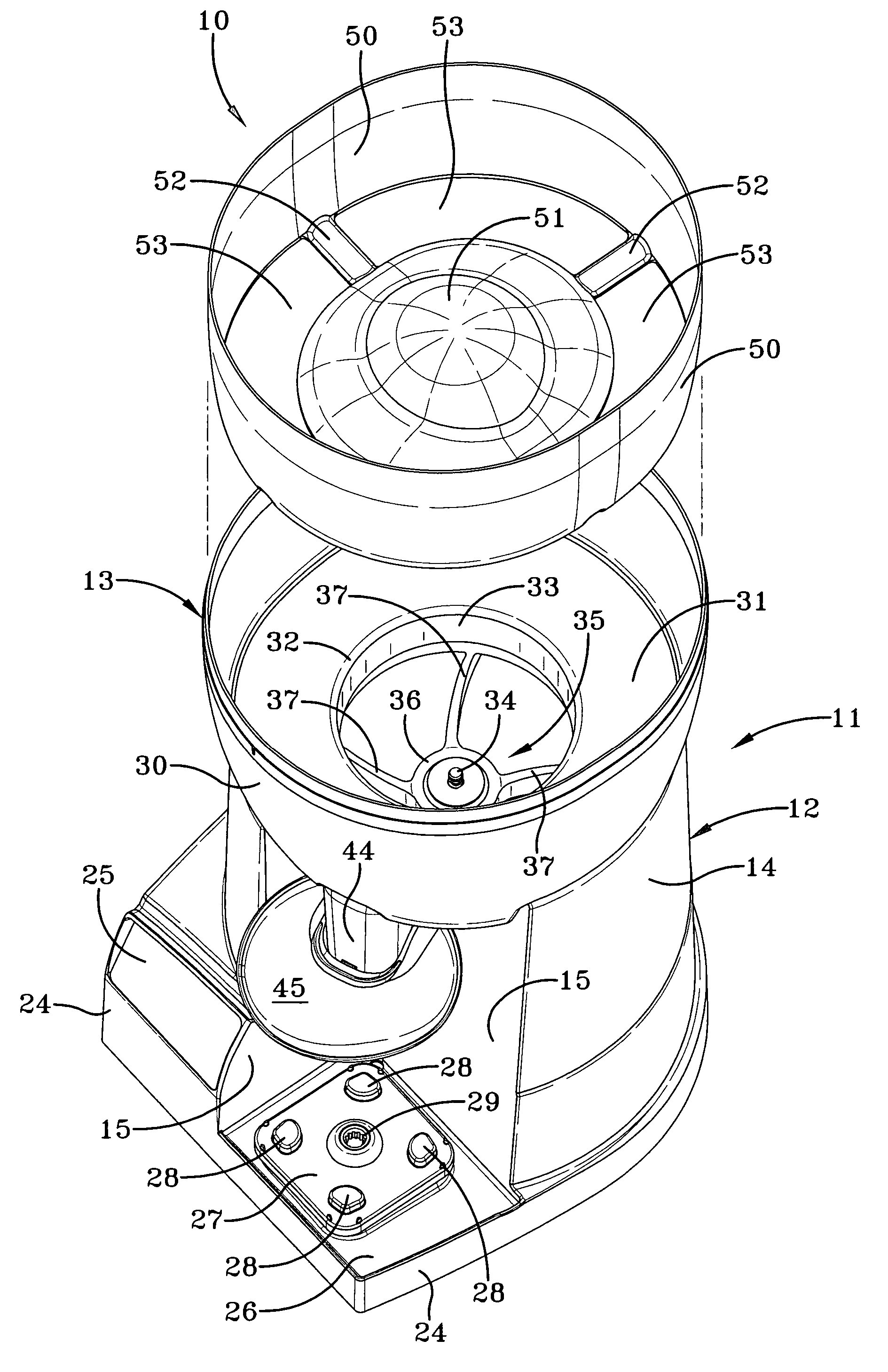
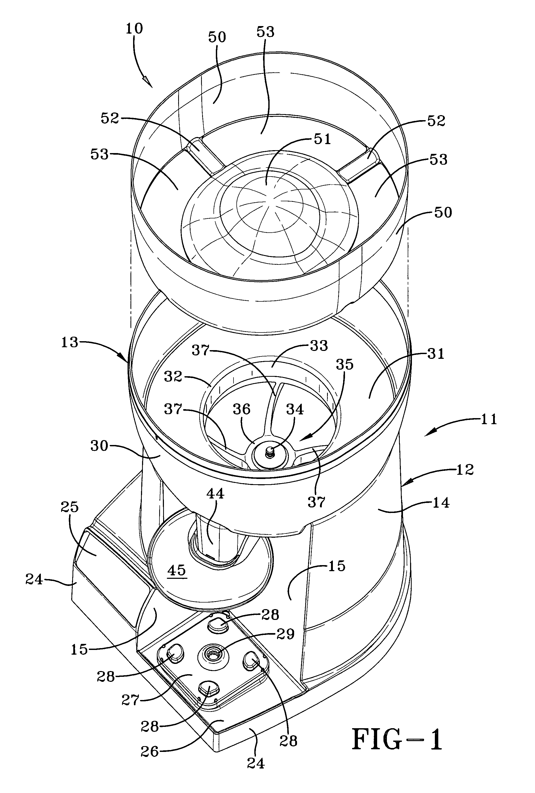
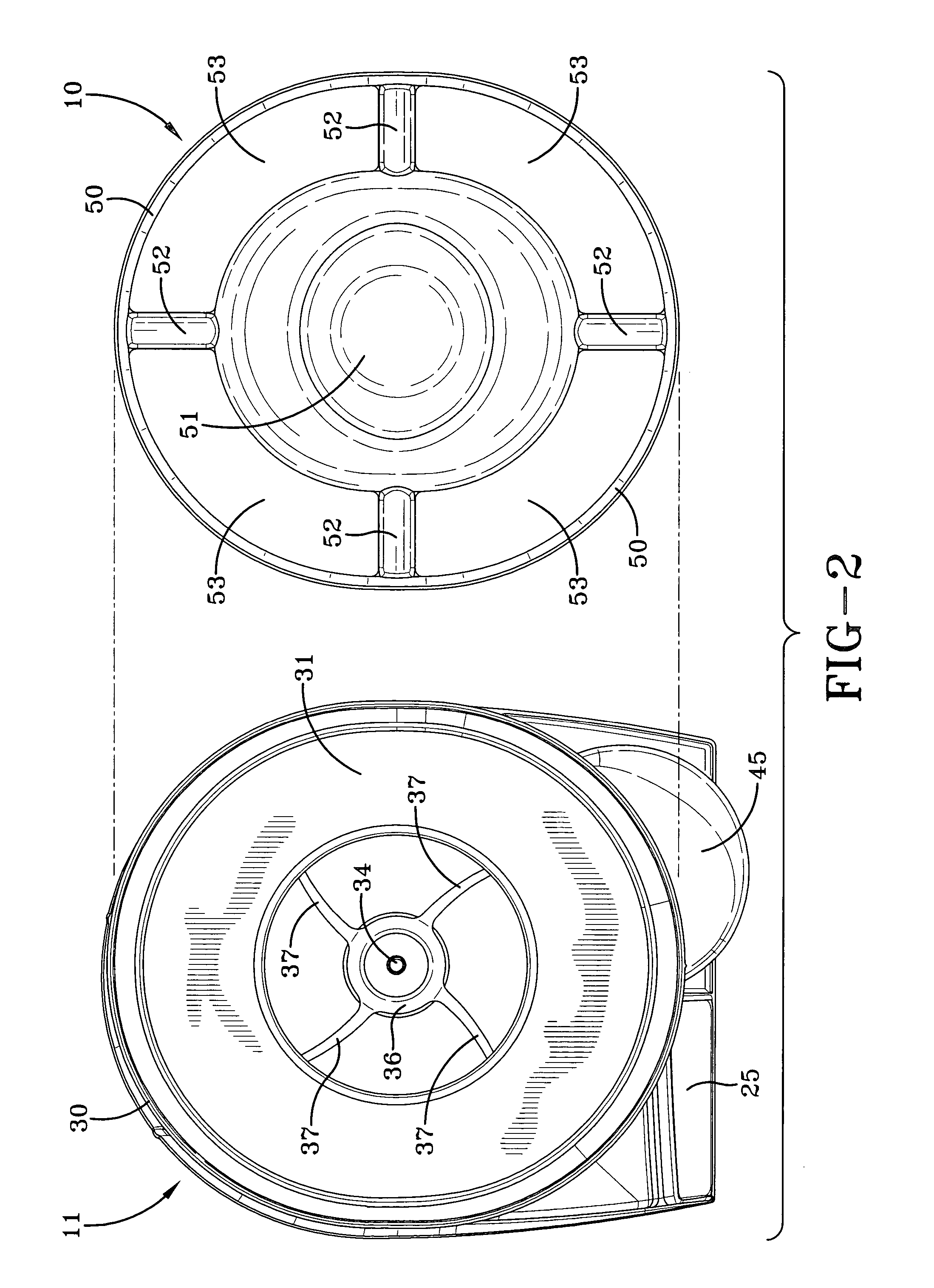
[0019] A safety shield device made in accordance with the present invention is indicated generally by the numeral 10 and is shown as being used with an ice shaving and dispensing machine generally indicated by the numeral 11. Ice shaver 11 can be of the type shown in U.S. Pat. No. 6,194,013 to which reference is made, as necessary, for a complete understanding of one environment in which safety shield 10 may be used.

[0020] Briefly describing some of the basic components of ice shaver 11, its function is to provide a predetermined amount of ice to a container, such as the pitcher of a blender. Ice shaver 11 includes a main housing or pedestal generally indicated by the numeral 12, and an ice bin generally indicated by the numeral 13. Pedestal 12 includes a generally upstanding cylindrical sidewall 14 interrupted by upstanding container walls 15. As shown in FIGS. 4 and 5, sidewall 14 and walls 15 have an upper rim 16 upon which a ledge 17 formed in bin 13 rests. Pedestal 12 also inc...


PUM


Abstract

A safety shield (10) is adapted to be used in a machine having a blade assembly such as an ice shaving and dispensing machine (11). The machine (11) has an ice bin (13) carried by a pedestal (12). An ice shelf (31) has an opening (32) and is positioned in the bin (13). The opening (32) provides access to the blade assembly which includes a shaver wheel (35) which directs ice to a blade (40). The shield (10) has a ring-shaped sidewall (50) which is carried by the bin (13) and which can extend upwardly out of the bin (13) to increase the capacity thereof. The shield (10) also includes a disk-shaped hub (51) which is connected to the side wall (50) by a plurality of arms (52). The hub (51) is larger than the opening (32) and is positioned over the opening (32) to prevent direct human access thereto. But ice may still pass through openings (53) between the arms (52) and through the opening (32) in the shelf (31) to be received by the blade assembly.

Description

TECHNICAL FIELD [0001] This invention relates to a device which prevents the user from contacting the blade components of a machine such as an ice shaving machine. More particularly, this invention relates to a device which allows user access to the bin of an ice shaving machine while at the same time preventing the user from making contact with the blade components thereof. BACKGROUND ART [0002] Machines which utilize blades to grind or otherwise cut food items such as ice or the like are most often required to provide safety features to prevent injury to the user. Typical of such machines is an ice shaving and dispensing machine such as shown in U.S. Pat. No. 6,194,013. In these devices, the blade components are positioned at the bottom of a bin which is adapted to receive a supply of ice which is to be shaved and which has a cover. [0003] Because the blade and other blade components could do serious damage to the hands of the user of the machine, most safety regulations currently...

Claims


Application Information

Patent Timeline
Patent Type & Authority Applications(United States)
IPC IPC(8): A23G9/04A23G9/22A47J43/046A47J43/07B01F15/00F16P1/02F25C5/12
CPCA23G9/045A23G9/228F25C5/12A47J43/0761F16P1/02A47J43/0727
Inventor KATZ, JONATHAN M.BOOZER, RICHARD D.RUKAVINA, STEPHEN P.LACHENDRO, JIMULANSKI, ROBERT M.
Owner VITA MIX MANAGEMENT
Why Eureka
Try Eureka