Centrifugal compressor and manufacturing method for impeller

a centrifugal compressor and manufacturing method technology, applied in the direction of marine propulsion, vessel construction, other chemical processes, etc., can solve the problems of efficiency and performance drop, and achieve the effects of reducing the throat width, reducing the separation and distortion of fluid, and reducing the change in flow ra

Inactive Publication Date: 2005-11-24
MITSUBISHI HEAVY IND LTD
View PDF5 Cites 41 Cited by
  • Summary
  • Abstract
  • Description
  • Claims
  • Application Information

AI Technical Summary

Benefits of technology

[0015] The centrifugal compressor according to the present invention, the impeller mounted with the plural blades radially is disposed rotatively in the inside of the casing, and the throat portion on the suction surface side in each blade is formed in a convex shape in a direction of blade height. Thus, a throat width is reduced, and a change in a flow path area in a direction of flow of fluid decreases and a change in a flow rate also decreases, along middle height of blade where Mach number is near unity. Therefore, an increase in a Mach number is controlled and a magnitude of a shock wave to be generated is also controlled, flow separation and distortion of the fluid decrease, and fall in efficiency and performance of the impeller is prevented. As a

Problems solved by technology

When this shock wave is large, there is a problem in that the flow sepa

Method used


Image

  • Centrifugal compressor and manufacturing method for impeller
  • Centrifugal compressor and manufacturing method for impeller
  • Centrifugal compressor and manufacturing method for impeller

Examples


first embodiment

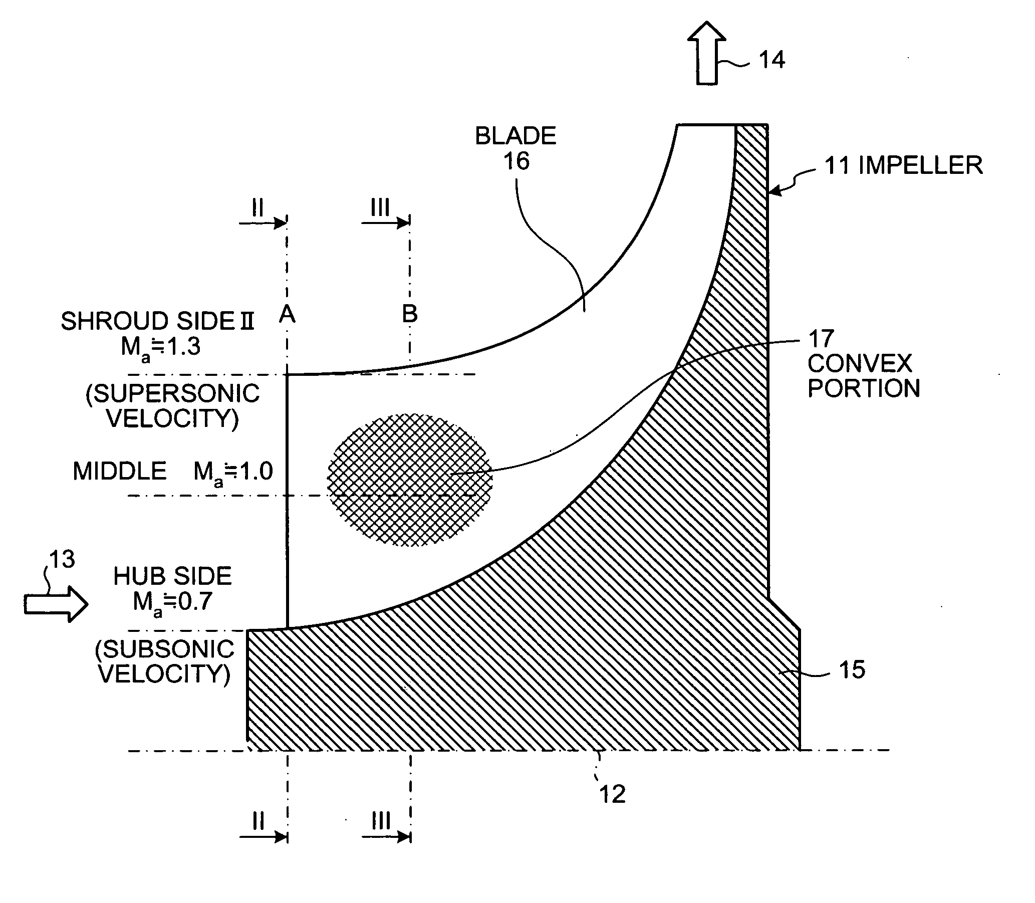
[0051] In this way, in the centrifugal compressor on the suction surface side of the blade 16 in the impeller 11, the convex portion 17 is formed to assume a curved line from the front edge portion A to the throat portion B substantially in the middle in the radial direction. This convex portion 17 is formed to be flat assuming a curved line from the throat portion B toward the rear edge portion, whereby this convex portion 17 is formed in a position where a relative inlet velocity of fluid into the impeller 11 is Mach number Ma≅1.

[0052] Therefore, the throat width is reduced in the middle of the impeller 11, a change in a flow path area in a direction of a flow of fluid is reduced, and a change in a flow rate per unit area is also reduced. Thus, an increase in a Mach number is controlled and a magnitude of a shock wave to be generated is also controlled, flow separation and distortion of a flow of the fluid decrease, and fall in efficiency and performance of the impeller 11 is pre...

second embodiment

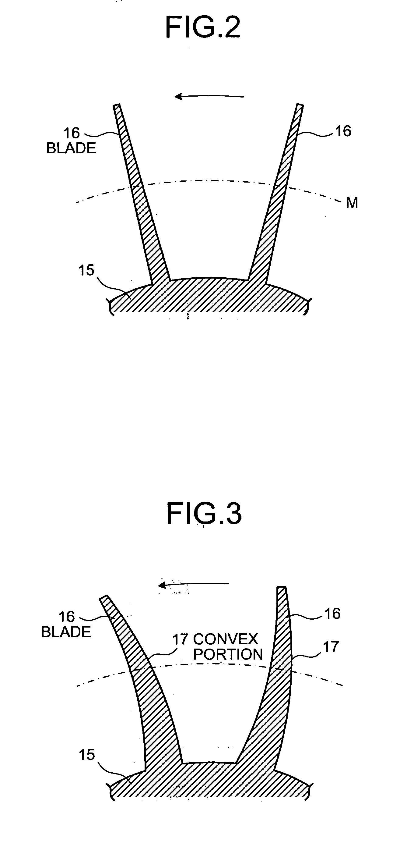
[0055] In the centrifugal compressor as shown in FIGS. 9 to 11, an impeller 31 is constituted in which plural blades 34 are fixed radially in an outer periphery of a hub 33 fixed to a rotary shaft 32. On a suction surface in the blade 34 of this impeller 31, a convex portion 35 is formed to gradually become convex assuming a curved line (arc shape) from the front edge portion A to the throat portion B, and this convex portion 35 is formed to gradually become plane from the throat portion B to the rear edge portion. Then, this convex portion 35 is formed to become a ridge substantially in the middle in the radial direction of the blade 34, that is, along a line on which a relative inlet velocity of fluid into the impeller 31 is Mach number Ma≅1.

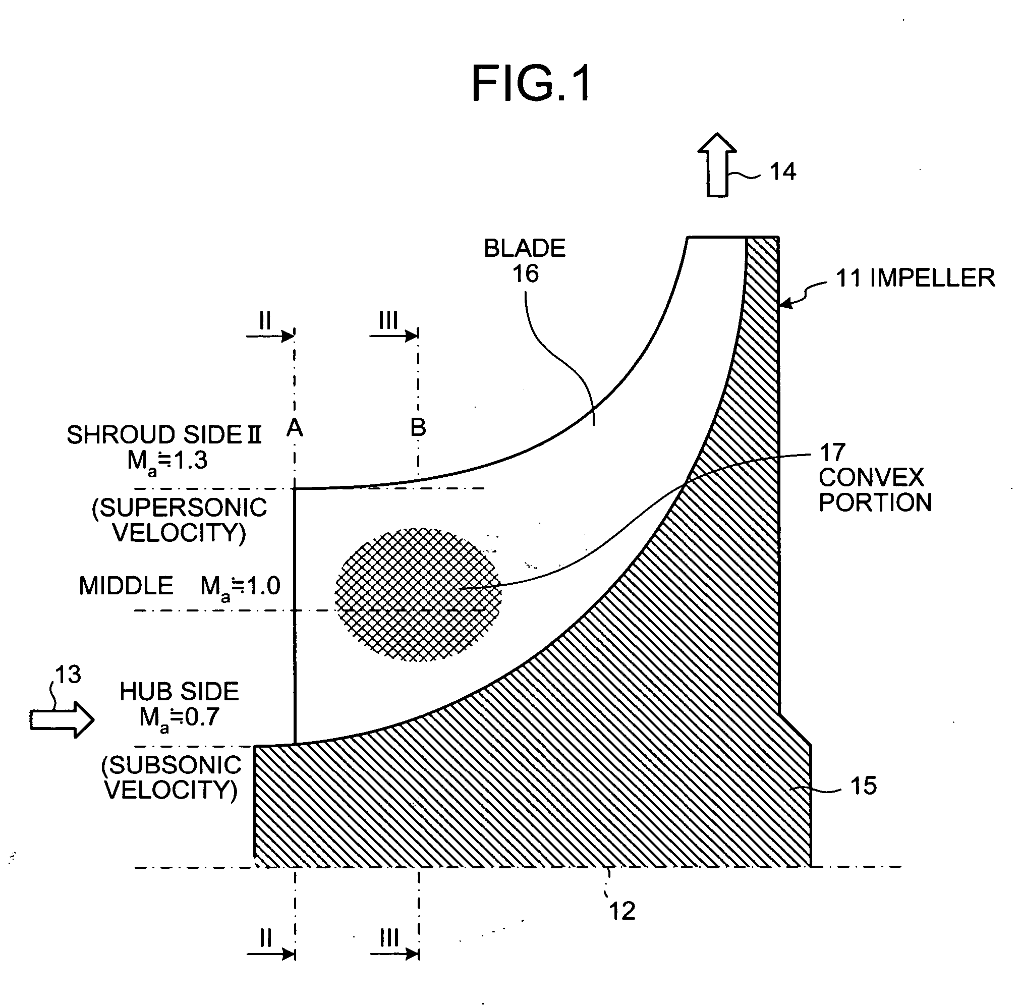
[0056] In this case, the blade 34 assumes a linear shape along the radial direction in the front edge portion A, and both a pressure surface side and a suction surface side thereof are flat. However, as shown in FIG. 10 in detail, the blade 3...

third embodiment

[0061]FIG. 13 is a sectional view of an impeller in a centrifugal compressor to the invention. Note that members having the same functions as those explained in the embodiments described above will be denoted by the identical reference numerals and signs and will not be explained repeatedly.

[0062] In the centrifugal compressor according to this embodiment, as shown in FIG. 13, in the impeller 31 according to the first embodiment the convex portion 35 is formed, or in the impeller 31 according to the second embodiment, the hub side of the convex portion 35 of the ridge shape is formed in a concave shape to form an impeller 41. In short, in the impeller 41 according to this embodiment, the convex portion 35 is formed to gradually become convex from the front edge portion to the throat portion on the suction surface in the blade 34. This convex portion 35 is formed same manner as the first embodiment 17, or same manner as the second embodiment to become a ridge substantially in the mi...


PUM


Abstract

On a suction surface side of a blade in an impeller, a convex portion is formed to assume a curved line from a front edge portion to a throat portion substantially in the middle in a radial direction, and this convex portion is formed to be flat assuming a curved line from the throat portion toward a rear edge portion, whereby this convex portion is formed in a position where a relative inlet velocity of fluid into the impeller is Mach number Ma≅1.

Description

BACKGROUND OF THE INVENTION [0001] 1) Field of the Invention [0002] The present invention relates to a centrifugal compressor that pressurizes fluid to change the fluid to compressed fluid, and in particular to an impeller for pressurizing fluid and a manufacturing method for the impeller. [0003] 2) Description of the Related Art [0004]FIG. 20 is a sectional view of an impeller in a conventional centrifugal compressor, FIG. 21 is a sectional view along line XXI-XXI in FIG. 20, FIG. 22 is a schematic diagram of shapes in respective positions in a blade of a conventional impeller, and FIG. 23 is a graph of a flow rate per a unit area with respect to a relative inlet velocity of fluid in the conventional centrifugal compressor. [0005] A general centrifugal compressor is constituted in which an impeller having plural blades is supported to rotate freely in a casing, an inlet passage along an axial direction with respect to this impeller is formed, and a diffuser along a radial direction...

Claims


Application Information

Patent Timeline
IPC IPC(8): F01D1/02F04D21/00F04D29/28F04D29/30F04D29/66
CPCF04D21/00F04D29/30F04D29/284F04D29/667F05D2210/12Y10S415/00Y10S416/00Y10S417/00
Inventor HIGASHIMORI, HIROTAKA
Owner MITSUBISHI HEAVY IND LTD
Why Eureka
Try Eureka