Method and coupling for repairing broken conduit

a technology of electrical and plumbing conduits, applied in the direction of manufacturing tools, instruments, transportation and packaging, etc., can solve the problems of time-consuming and expensive projects for repairing broken conduit ends and encasing concrete foundations in concrete foundations

Active Publication Date: 2005-12-01
THOMAS & BETTS INT INC
View PDF33 Cites 8 Cited by
  • Summary
  • Abstract
  • Description
  • Claims
  • Application Information

AI Technical Summary

Benefits of technology

[0006] The method and specialized repair component for repairing broken conduit ends of this invention eliminates the need to break up the concrete foundation around the broken conduit end. The specialized repair components include a reaming bit for milling out and turning down the inside wall of the broken conduit end and repair couplings for joining a new section of conduit to the broken conduit end. The reaming bit is designed to be used with any conventional handheld power drill. The reaming bit mills out the inside of the broken conduit end so that the repair coupling can be inserted into the broken conduit end. With the coupling fitted into the broken conduit end, a new section of conduit can be connected completing the repair. Because the coupling is inserted into the broken end of the conduit instead of over it, the concrete foundation around the conduit does not have to be disturbed. Consequently, this repair method provides a structurally more secure repair.
[0007] Accordingly, an advantage of this invention is that the method eliminates the need to breakup concrete foundations surrounding the broken conduit end, which greatly reduces the time and expense of the repair.
[0008] Another advantage of this invention is that the repair method provides a more structurally secure repair because the concrete foundation remains undisturbed.
[0010] Another advantage of this invention is that the reaming bit is designed to be used in any conventional handheld power drill, which is common and readily available at any construction site.
[0011] Another advantage of this invention is that a single user in only a few minutes can prepare a large number of broken conduit ends for repair, turning down the inside walls of the conduit with the drill mounted reaming bit.

Problems solved by technology

Repairing the broken conduit embedded in a concrete foundation is an expensive and time consuming project.
Repairing broken conduit ends is a time consuming expense that is not factored into the cost of most construction projects.

Method used


Image

  • Method and coupling for repairing broken conduit
  • Method and coupling for repairing broken conduit
  • Method and coupling for repairing broken conduit

Examples


Embodiment Construction

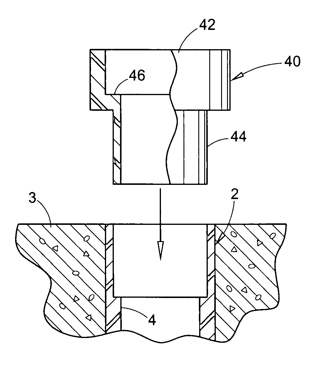
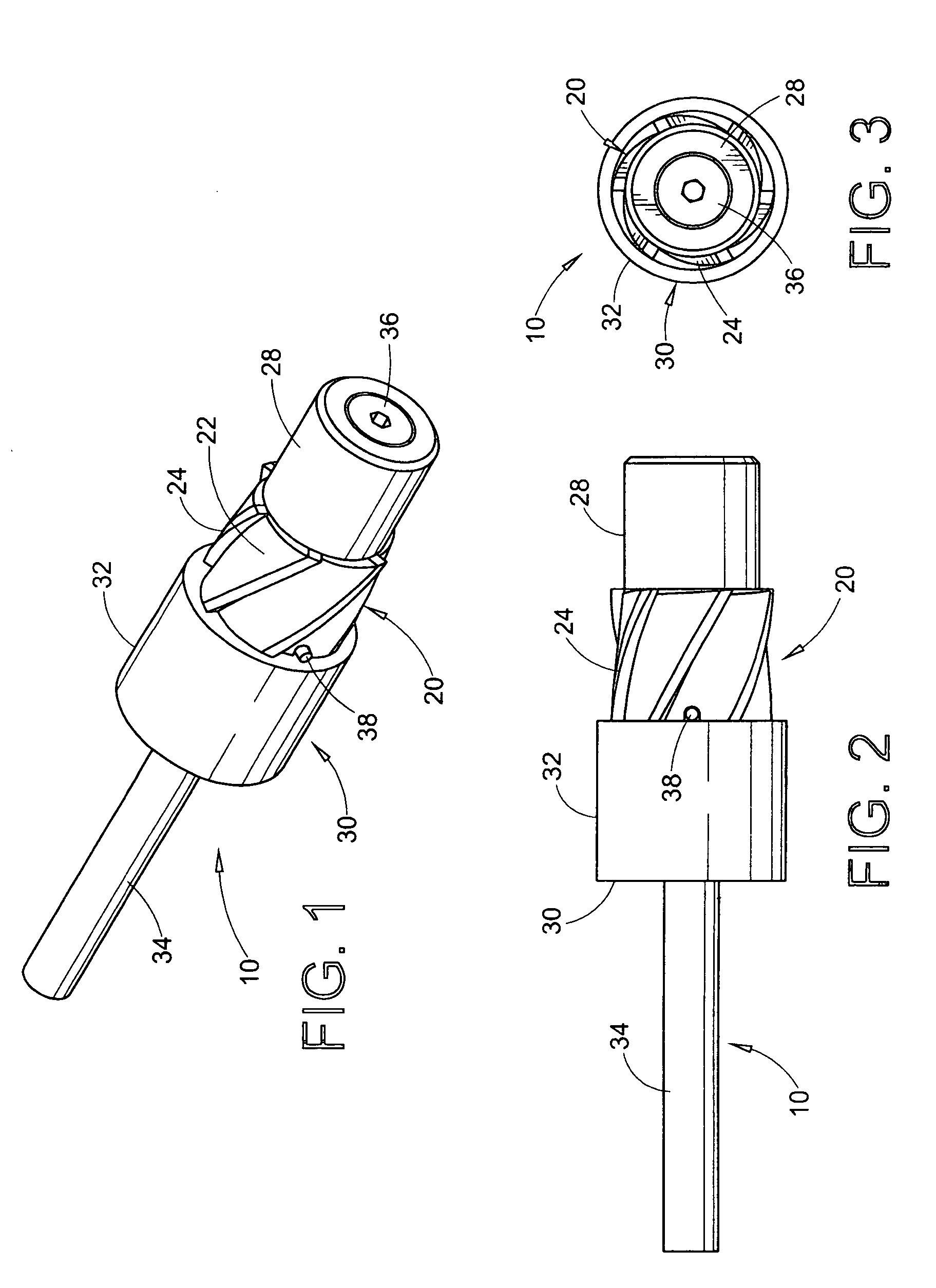
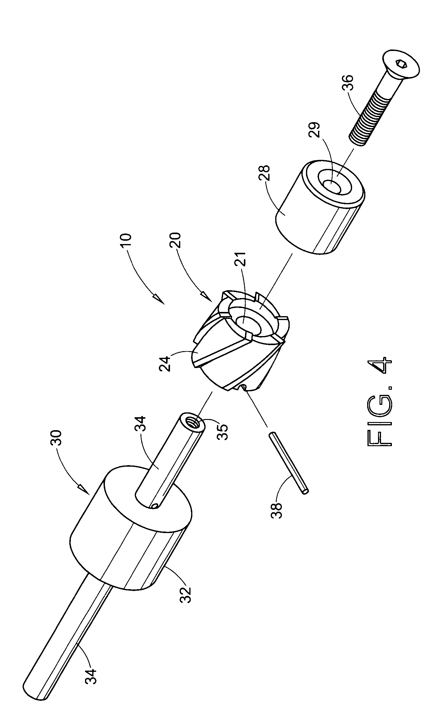
[0026] The preferred embodiment herein described is not intended to be exhaustive or to limit the invention to the precise form disclosed. It is chosen and described to best explain the invention so that others skilled in the art might utilize its teachings. This invention entails a method of repairing broken electrical conduit embedded in a concrete foundation without breaking up the foundation and the specialized components used in the repair, namely, a reaming bit and various embodiments of a repair coupling.

[0027]FIGS. 1-4 illustrate the specialized reaming bit of this invention (designated generally as reference numeral 10), which is used to bore out the inner wall of the broken conduit end. Reaming bit 10 has a conventional design and construction common for drill and milling tools and is intended for use with hand held power drills (reference numeral 8 in FIGS. 5 and 6). As shown, reaming bit 10 includes an interchangeable cutting head 20 and pilot head 28 mounted on a mandr...


PUM

PropertyMeasurementUnit
diameteraaaaaaaaaa
thicknessaaaaaaaaaa
thicknessaaaaaaaaaa

Abstract

Broken conduit is repaired by enlarging the inner diameter at the broken end portion to provide a socket for receiving a coupling that has a male end portion with a reduced radial wall thickness and is configured so that the external diameter of the male end portion is closely received in the socket while the inner diameter thereof corresponds to the original inner diameter of the conduit.

Description

REFERENCE TO RELATED APPLICATIONS [0001] This application is a division of U.S. Ser. No. 10 / 610,042 filed Jun. 30, 2003.BACKGROUND OF THE INVENTION [0002] This application relates to a method of repairing broken electrical and plumbing conduit that extends outward from concrete foundations. [0003] Electrical conduit is often embedded in concrete foundations and floors of commercial and residential buildings, so that electrical wiring can be run at a later time. Since concrete foundations and floor are poured before any internal walls and other structures are erected, short sections of conduits extend vertically above the foundation and floor at every location of an electrical source. In large construction projects, there may be hundreds of exposed conduit ends extending from the concrete foundation and floors. In the course of construction, these exposed ends of the electrical conduit are often broken off by workers and equipment in the course of moving materials, erecting interior ...

Claims


Application Information

Patent Timeline
Patent Type & Authority Applications(United States)
IPC IPC(8): B23B51/00B23D77/00B23P6/00F16L55/16H01H1/00
CPCB23D77/00Y10T29/49004Y10T29/4973Y10T29/49995Y10T408/8925Y10T29/49174Y10T29/49718Y10T29/49725Y10T29/49726Y10T408/03Y10T408/90993Y10T29/53213Y10T408/8923Y10T408/5584B23D2277/68
Inventor KEIPER, MICHAEL C.
Owner THOMAS & BETTS INT INC
Why Eureka
Try Eureka