
Linearity calibration standard for fiber optic power meters

a fiber optic power meter and linear calibration technology, applied in the field of integrated systems, can solve the problems of time-consuming and expensive, low-end optical power meter, handheld optical power meter, etc., and achieve the effect of reducing time and expens

Inactive Publication Date: 2014-02-25
THE US SEC THE NAVY CHIEF OF NAVAL RES OFFICE OF COUNSEL
View PDF0 Cites 0 Cited by
  • Summary
  • Abstract
  • Description
  • Claims
  • Application Information

AI Technical Summary

Benefits of technology

This patent describes a new system that makes it faster and cheaper to calibrate fiber optic power meters. The system uses a special method called triplet superposition, which helps make the necessary measurements. Overall, this system makes it easier to ensure the accuracy of fiber optic power meters.

Problems solved by technology

The calibration of OLTSs is an issue that has been standardized by recognized standards organizations.
Conventional optical power meter linearity measurement requires manual setup and operation, which is time-consuming and expensive.
However, lower-end optical power meters, such as handheld optical power meters, do not typically have such control and measurement interfaces.

Method used


Image

  • Linearity calibration standard for fiber optic power meters
  • Linearity calibration standard for fiber optic power meters
  • Linearity calibration standard for fiber optic power meters

Examples


Embodiment Construction

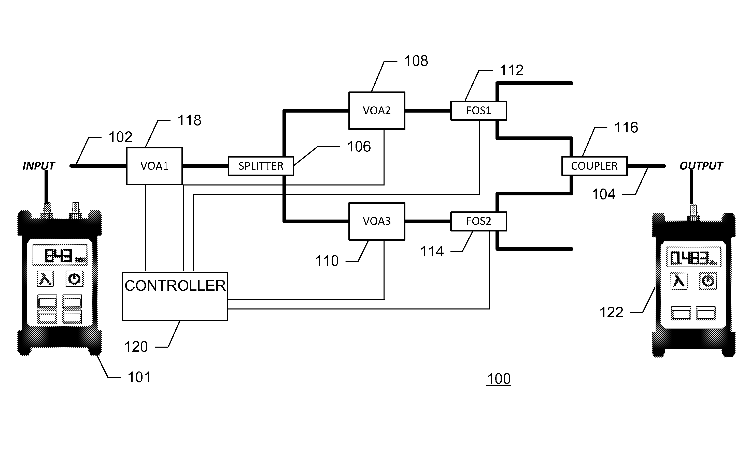
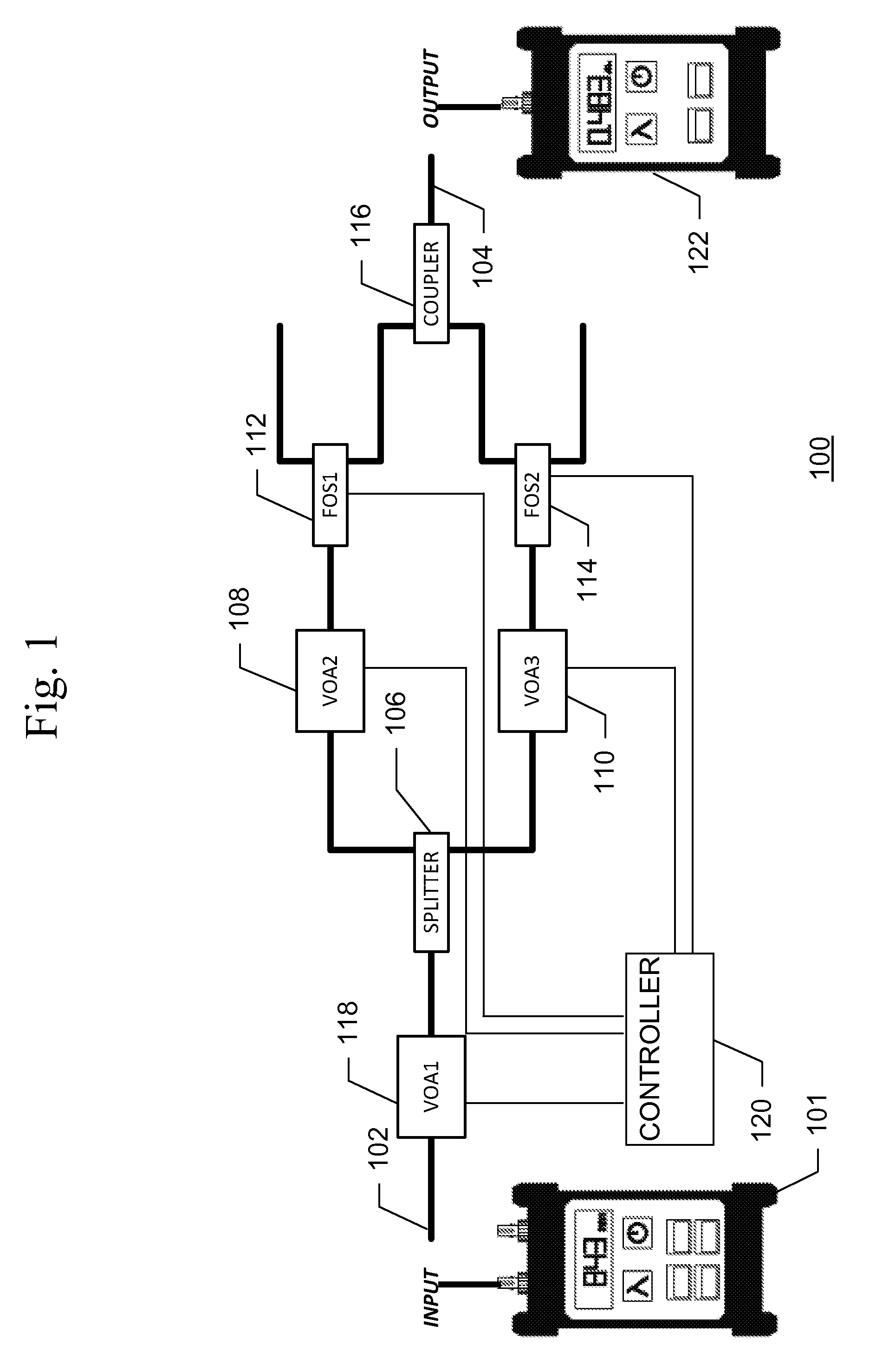
[0016]An integrated, automated system for determining the linearity of measurements of fiber optic power meters reduces the time and expense needed for linearity calibration. The system uses the triplet superposition method of linearity calibration and provides the proper conditions at each desired power level for an operator to take the necessary measurements.

[0017]The triplet superposition method includes of a set of three measurements. The power meter under test is stimulated with an arbitrary amount of optical power, and a measurement is made by the power meter under test. A second source of power is used to stimulate the power meter and a second measurement is taken. The third measurement is taken while simultaneously stimulating the power meter with both power sources. The third power level is the sum of the first two power levels. The non-linearity at this power level is the difference between the measured power level and the sum of the two power levels. This process is repea...


PUM


Abstract

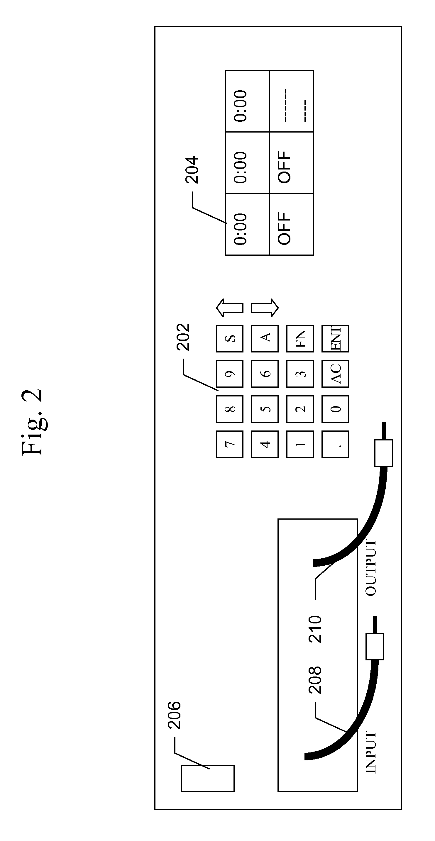
An integrated, more automated system for determining the linearity of measurements of fiber optic power meters reduces the time and expense needed for linearity calibration. The system uses the triplet superposition method of linearity calibration and aids in performing the necessary series of measurements. A linearity measurement system for an optical power meter comprises an apparatus to output an optical signal to the optical power meter, the apparatus configured to output the optical signal at a controllable plurality of optical powers, a controller for controlling an optical power output from the apparatus to the optical power meter, a display device for displaying a state of the apparatus based on information from the controller, and an input device for commanding the controller to control the optical power output from the apparatus to the optical power meter.

Description

BACKGROUND OF THE INVENTION[0001]1. Field of the Invention[0002]The present invention relates to an integrated system for automatically providing the proper conditions to make linearity of measurements of fiber optic power meters.[0003]2. Description of the Related Art[0004]An optical loss test set (OLTS) consists of an optical power meter and an optical power source. Fiber optic communications systems typically use 850-nm or 1300-nm optical sources for multimode fiber optic networks, and 1310-nm or 1550-nm sources for single mode fiber optic networks. The OLTS power sources also produce optical signals at these wavelengths, and the optical power meter is calibrated to measure the power at each of these wavelengths. The OLTS is capable of making both absolute and relative power measurements. However, the most common measurement of interest taken by the OLTS is the relative power measurement. The typical OLTS provides a measurement range of at least 60 dB in most cases, and in some c...

Claims


Application Information

Patent Timeline
Patent Type & Authority Patents(United States)
IPC IPC(8): G02B6/00
CPCG01J1/0219G01J1/0488G01D5/268G01M11/00G01J1/0425G01J1/0233G01J1/0418
Inventor DODDRIDGE, LANCE, S
Owner THE US SEC THE NAVY CHIEF OF NAVAL RES OFFICE OF COUNSEL
Learn More