
Air flow measurement system having reduced sensitivity to flow field changes

a flow measurement and sensitivity technology, applied in the direction of volume/mass flow measurement, measurement devices, instruments, etc., can solve the problem and achieve the effect of reducing sensitivity to upstream duct configuration variations and maintaining air attachmen

Inactive Publication Date: 2005-12-01
DELPHI TECH INC
View PDF1 Cites 18 Cited by
  • Summary
  • Abstract
  • Description
  • Claims
  • Application Information

AI Technical Summary

Benefits of technology

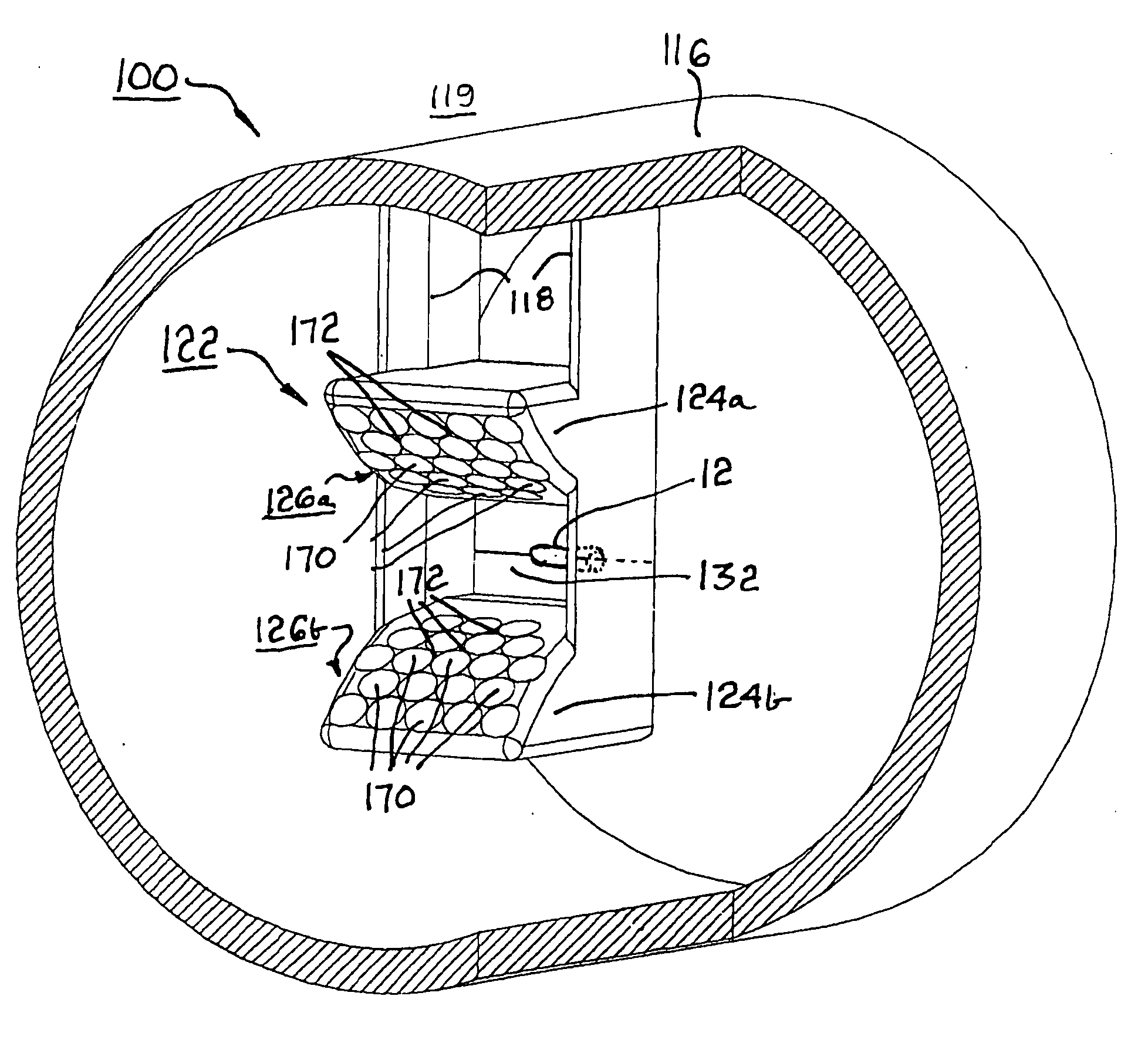
[0014] Briefly described, an air flow measurement system for measuring air flow rate in a duct includes an air flow sensor and an air flow conditioning device for collecting and accelerating toward the sensor a portion of the total air stream flowing through the duct. The sensor may be a conventional hot wire or other means as is known in the art. The conditioning device includes at least two opposed converging walls defining a nozzle, preferably a venturi, the sensor being disposed in the throat of the nozzle. The surfaces of the venturi walls are textured to create local cells of turbulence in the air boundary layer near the wall surface. Tripping the boundary layer flow into turbulence energizes the boundary layer and aids in maintaining attachment of flowing air to the walls even when the angle of attack of the air is significantly non-axial. The wall texturing may be random or may be an organized pattern. A currently preferred tripping pattern is a dimpled array similar to the surface of a golf ball. Keeping the boundary layer attached to the surface results in an effective throat area that does not change significantly with changes in the upstream flow field and angle of attack of incoming air to the air flow conditioner. Hence the flow profile through the throat and over the sensor remains similar to the profile produced with parallel walls and results in reduced sensitivity to variations in the upstream duct configurations.

Problems solved by technology

Hence the flow profile through the throat and over the sensor remains similar to the profile produced with parallel walls and results in reduced sensitivity to variations in the upstream duct configurations.

Method used


Image

  • Air flow measurement system having reduced sensitivity to flow field changes
  • Air flow measurement system having reduced sensitivity to flow field changes
  • Air flow measurement system having reduced sensitivity to flow field changes

Examples


Embodiment Construction

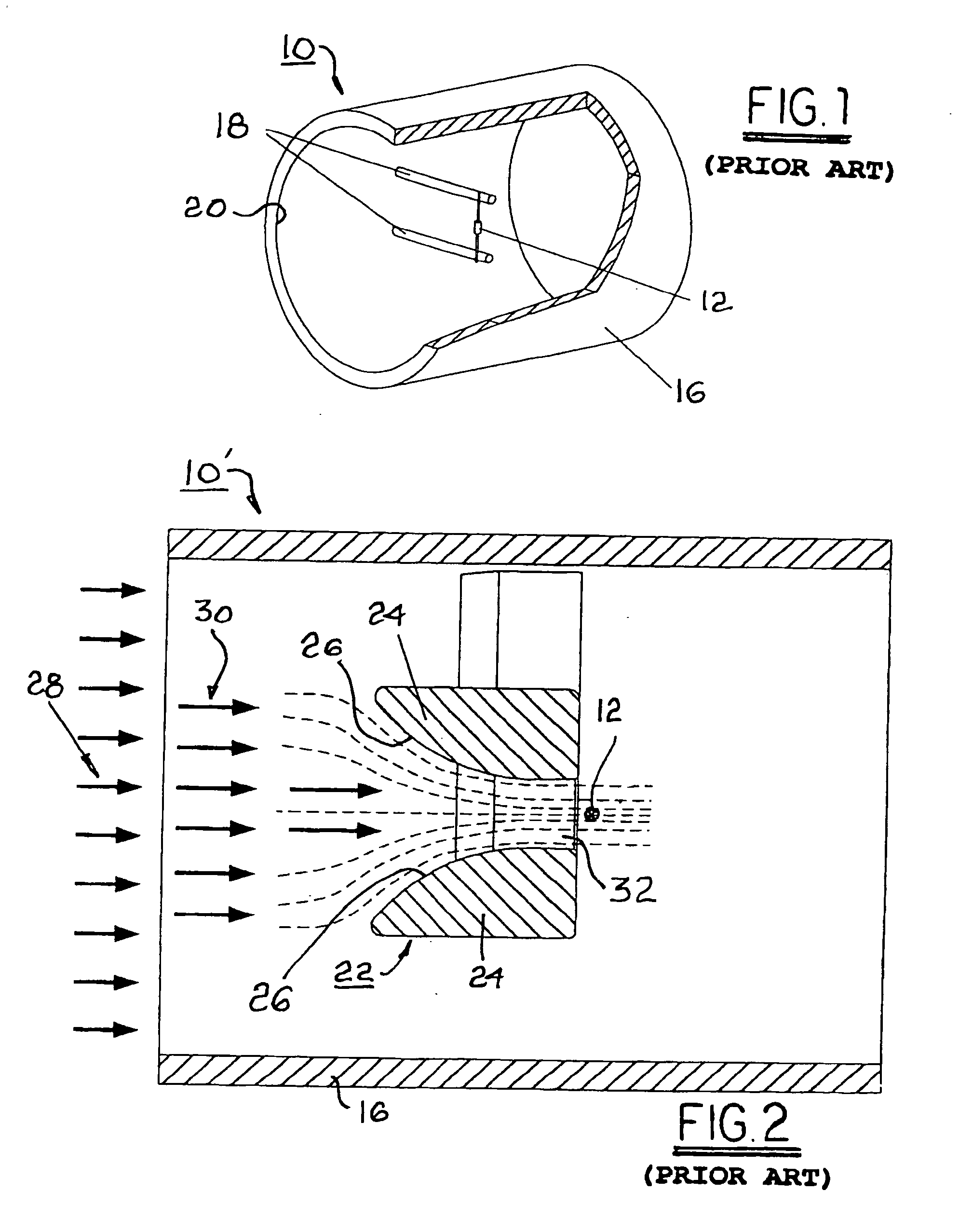
[0029] Referring to FIG. 1, a first prior art air flow measurement system 10 includes a flow sensor 12 disposed in the interior of a cylindrical duct 16 for conveying air and attached by supports 18 to the interior wall 20 of duct 16. System 10 includes no upstream air flow conditioning means; thus sensor 12 samples only a tiny region of the cross-sectional area of duct 16 and is therefore highly sensitive to turbulent flow around the sensor, as may occur due to turbulence-generating changes in the upstream ducting (not shown in FIG. 1). Even if total flow rate remains fixed, any changes to the upstream ducting configuration can alter the flow field around the sensor and cause the sensor output to change. The air flow signal will then contain a degree of error.

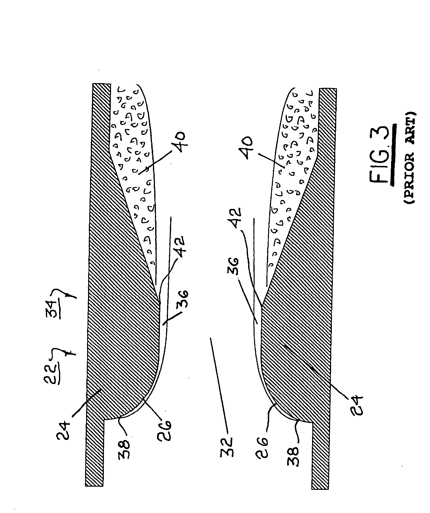
[0030] Referring to FIG. 2, a second prior art air flow measurement system 10′ includes a flow sensor 12 but also includes a venturi nozzle air flow conditioning device 22 disposed in duct 16 upstream of sensor 12. Device 22 ...


PUM


Abstract

A system for measuring air flow rate in a duct includes an air flow sensor and an air flow conditioning device for collecting and accelerating a portion of the total air stream to the sensor, which may be means as known in the art. The conditioning device includes two opposed converging walls defining a nozzle, preferably a venturi, the sensor being disposed in the throat of the nozzle. The surfaces of the venturi walls are textured to trip the boundary layer near the wall surface into turbulence to maintain attachment of flowing air to the walls even when the angle of attack of the air is significantly non-axial. The wall texturing may be random or may be an organized pattern. A further embodiment includes a second flow conditioner / sensor in parallel with the first whereby an averaged flow measurement is taken for a more accurate reading.

Description

TECHNICAL FIELD [0001] The present invention relates to systems for measuring the flow velocity, flow volume, or mass flow rate of a gas through a conduit; more particularly, to such systems having convergent walls for forming a laminar flow of gas past a sensor; and most particularly, to such a system having a textured wall surface for creating turbulent flow in the wall boundary layer in the wall-convergence zone to maintain wall contact with gas flows approaching from off-axis directions. BACKGROUND OF THE INVENTION [0002] Air flow measurement systems incorporating any of various types of sensor elements are well known, for example, a heated wire whose temperature is an inverse function of the velocity of air flowing past the wire. In most air flow measurement devices, the sensor interacts with only an extremely small portion of the total flow field, typically central to the field. It is a well known problem in the design and use of air flow measurement devices that changes in up...

Claims


Application Information

Patent Timeline
IPC IPC(8): G01F1/68G01F1/684G01F5/00
CPCG01F5/00G01F1/6842
Inventor EMMERT, CHARLES G. JR.EMMERT, DAN H.FIZELL, EDWARD R.KNIEPER, CHRISTOPHER H.
Owner DELPHI TECH INC
Learn More