Cookware apparatus

a technology for cooking and apparatus, applied in the field of cooking, can solve problems such as valve leakage and potential problems that can occur

Inactive Publication Date: 2005-12-01
GOLDING ERIC
View PDF15 Cites 8 Cited by
  • Summary
  • Abstract
  • Description
  • Claims
  • Application Information

AI Technical Summary

Benefits of technology

[0011] To achieve the foregoing and other advantages, the present invention, briefly described, provides cookware apparatus which includes a container portion which includes a container bottom and a container side wall which extends upward from the container bottom. The container side wall has a side wall top and has an exterior side wall surface. A spout portion is connected to the container side wall between the side wall top and the container bottom. The spout portion extends outward from the exterior side wall surface along a spout axis and is in fluid communication with an interior container space of the container portion. A handle is connected to the container side wall and extends along a longitudinal handle axis. The spout axis extends transversely with respect to the longitudinal handle axis. Use of the invention permits a user to pour off unwanted liquids from the interior container space without worrying about also pouring out desired solid food from the interior container space.

Problems solved by technology

In addition, having a drainage valve brings up potential problems that can occur when a valve is employed.
Valves often leak after extended use.
Thus, while the foregoing body of prior art indicates it to be well known to use cookware that has oil and grease drainage features, the prior art described above does not teach or suggest a cookware apparatus which has the following combination of desirable features: (1) does not have a relatively high and wide cylindrical drainage receiving receptacle that is supported by a funnel-like side projection from the cookware; (2) does not employ a drainage valve; and (3) does not include a drainage spout that is located along the longitudinal axis of the cookware handle.

Method used


Image

  • Cookware apparatus
  • Cookware apparatus
  • Cookware apparatus

Examples


Embodiment Construction

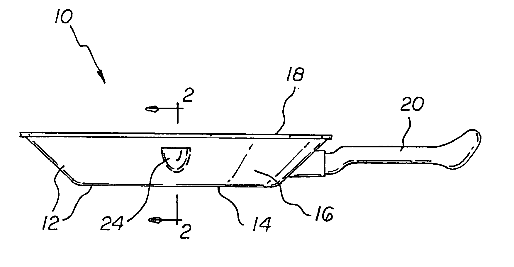
[0032] With reference to the drawings, a new and improved cookware apparatus embodying the principles and concepts of the present invention will be described.

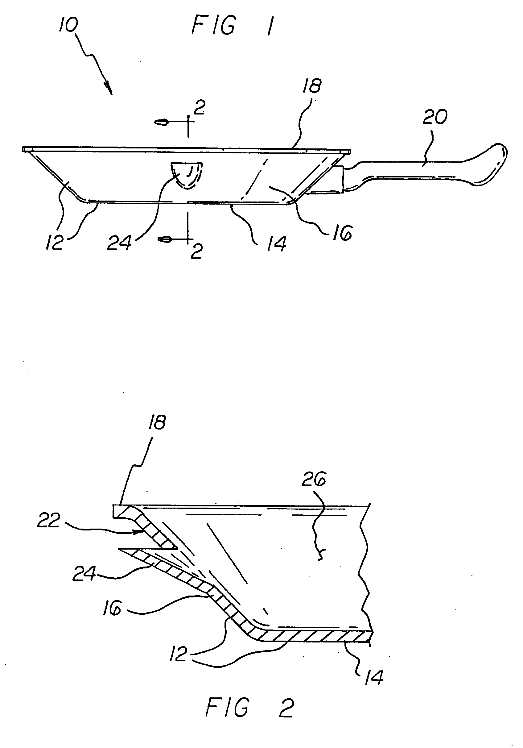
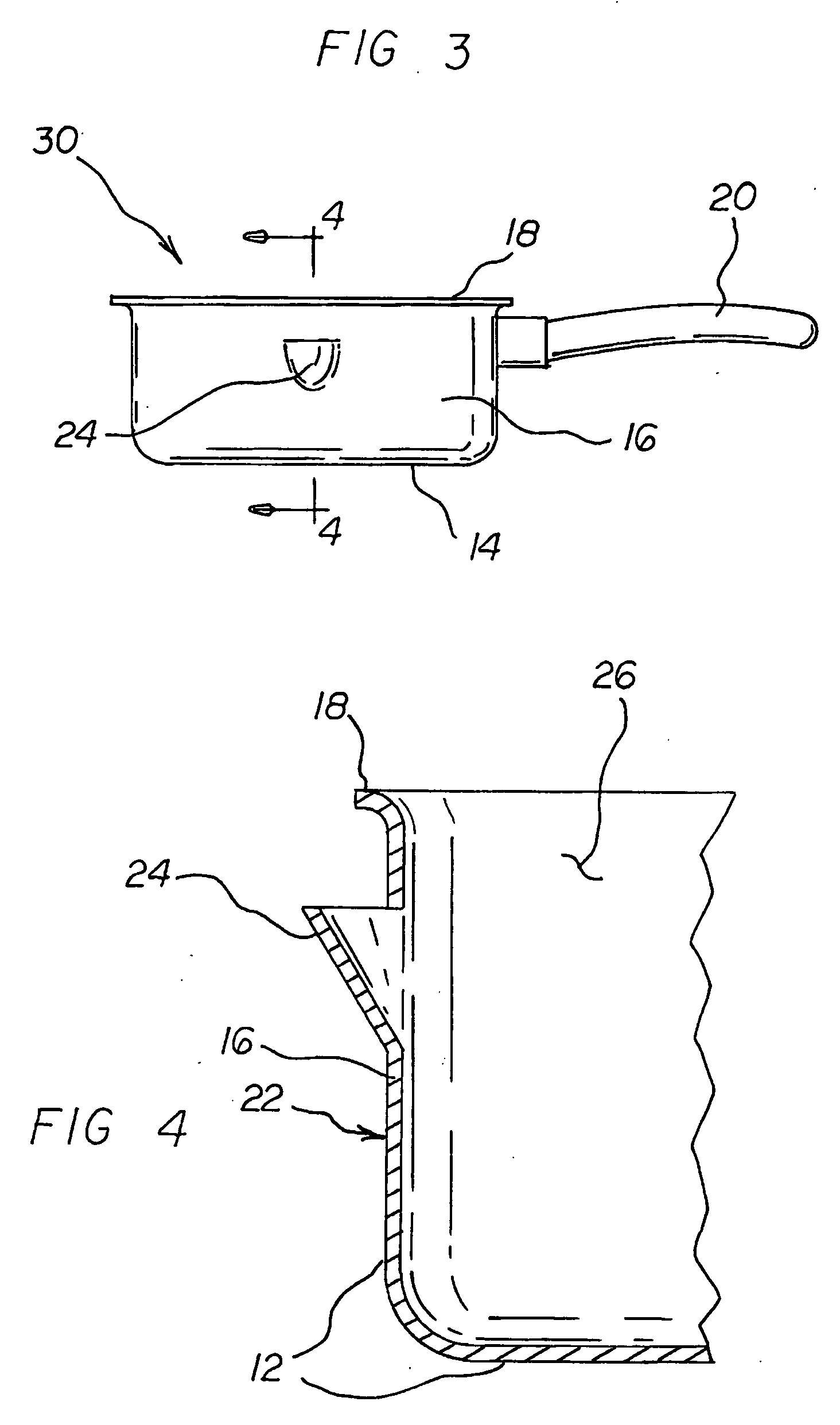
[0033] Turning to FIGS. 1, 2, 5, and 6, there is shown a first embodiment of the cookware apparatus of the invention generally designated by reference numeral 10. In the first embodiment, cookware apparatus 10 includes a container portion 12 which includes a container bottom 14 and a container side wall 16 which extends upward from the container bottom 14. The container side wall 16 has a side wall top 18 and has an exterior side wall surface 22. A spout portion 24 is connected to the container side wall 16 between the side wall top 18 and the container bottom 14. The spout portion 24 extends outward from the exterior side wall surface 22 along a spout axis 28 and is in fluid communication with an interior container space 26 of the container portion 12. A handle 20 is connected to the container side wall 16 and extends along a...


PUM


Abstract

A cookware apparatus includes a container portion which includes a container bottom and a container side wall which extends upward from the container bottom. The container side wall has a side wall top and has an exterior side wall surface. A spout portion is connected to the container side wall between the side wall top and the container bottom. The spout portion extends outward from the exterior side wall surface along a spout axis and is in fluid communication with an interior container space of the container portion. A handle is connected to the container side wall and extends along a longitudinal handle axis which extends transversely with respect to the spout axis. Use of the invention permits a user to pour off unwanted liquids from the interior container space without worrying about also pouring out desired solid food from the interior container space. The apparatus can be in the form of a frying pan, skillet, or cooking pot.

Description

CROSS-REFERENCE TO RELATED APPLICATION [0001] This application claims priority based upon my copending Provisional Application Ser. No. 60 / 575,782; filed Jun. 1, 2004.BACKGROUND OF THE INVENTION [0002] 1. Field of the Invention [0003] The present invention relates generally to cookware, and, more particularly, to cookware especially adapted for draining oil or grease from the cookware. [0004] 2. Description of the Prior Art [0005] When a cook uses cookware for cooking with oil or grease, it is often desirable to remove some of the hot oil grease from the cookware. In this respect, throughout the years, a number of innovations have been developed relating to cookware that have features for draining oil or grease from the cookware, and the following U.S. patents are representative of some of those innovations: U.S. Pat. Nos. 2,157,303, 3,218,959, and 4,352,324. [0006] U.S. Pat. No. 2,157,303 discloses a draining frying pan which includes a funnel-like projection which projects outward...

Claims


Application Information

Patent Timeline
Patent Type & Authority Applications(United States)
IPC IPC(8): A47J36/14A47J37/10
CPCA47J36/14
Inventor GOLDING, ERIC
Owner GOLDING ERIC
Why Eureka
Try Eureka