

Fuel delivery system
- Summary
- Abstract
- Description
- Claims
- Application Information
AI Technical Summary
Benefits of technology
Problems solved by technology
Method used
Image

Examples
first embodiment
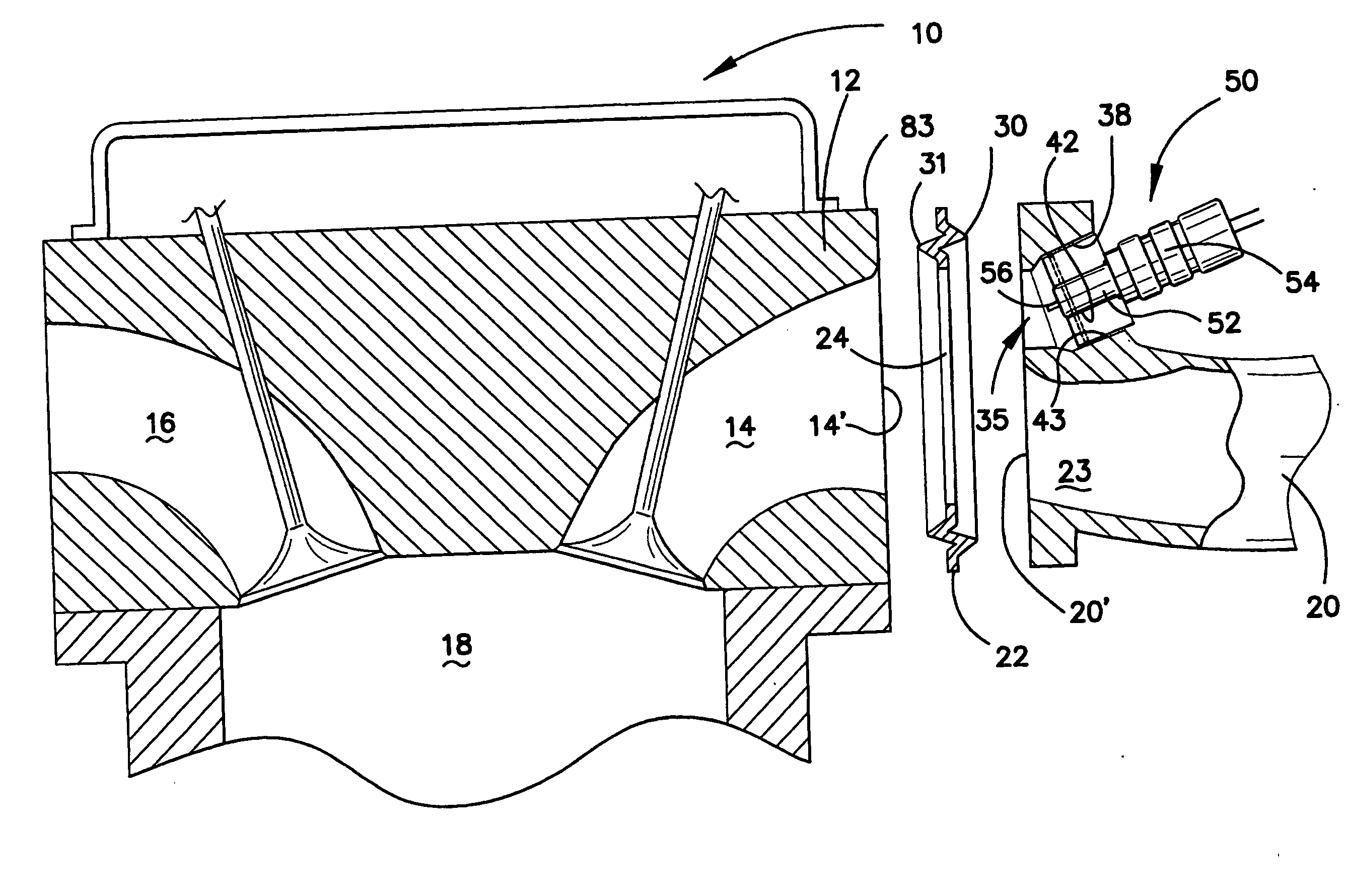
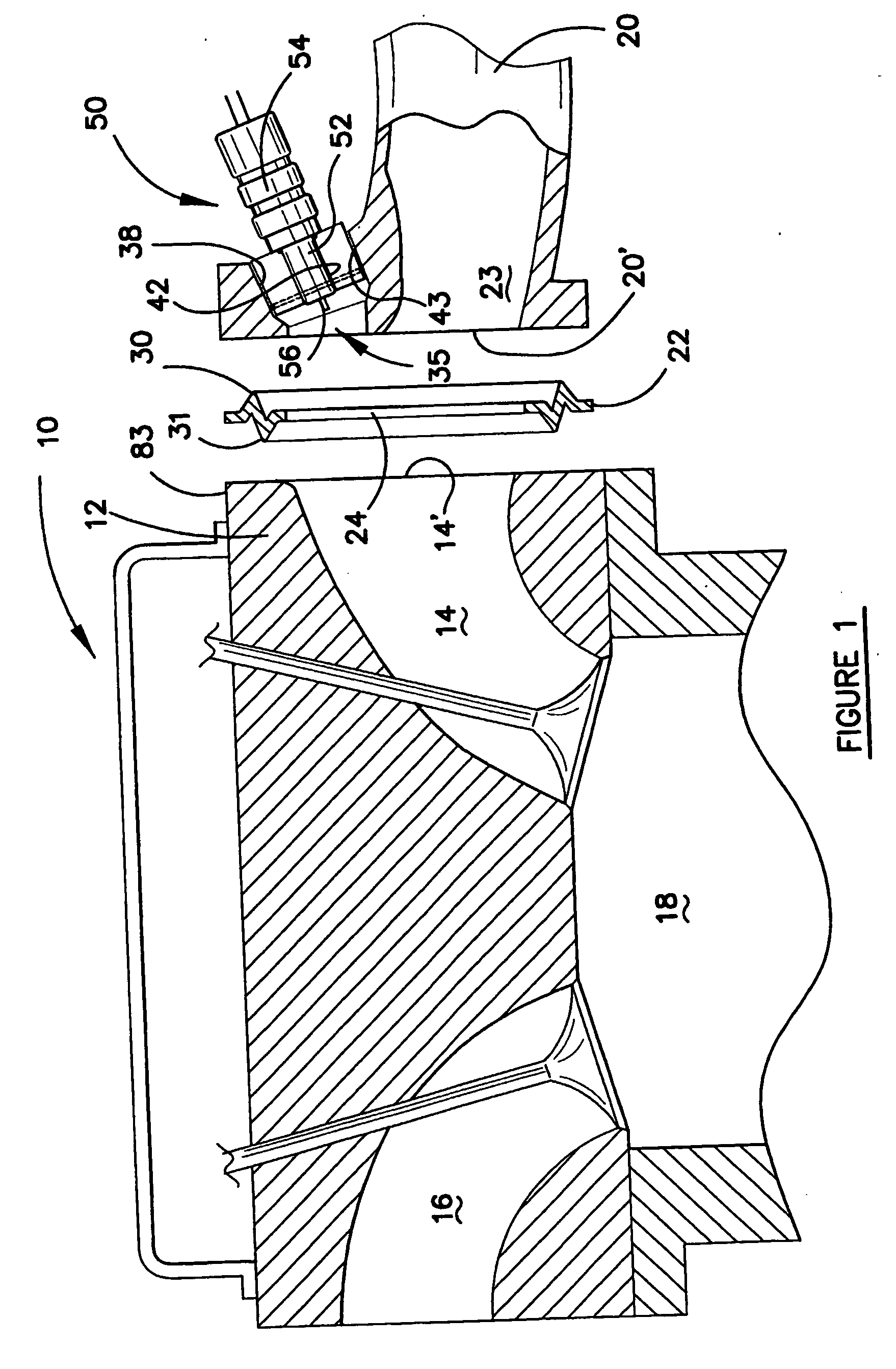
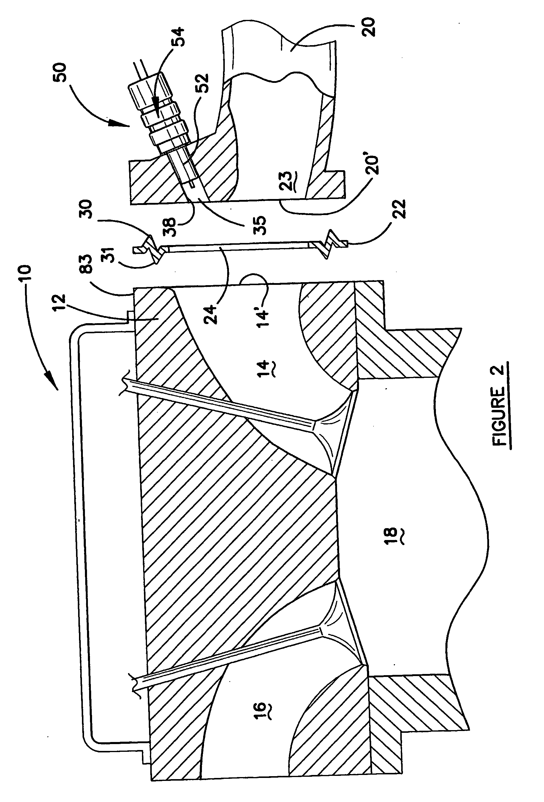
[0107] In the present invention, the injector 50 has its seals and outer casing (neither of which is shown) removed, so as to expose end region 52. The end region 52 is formed from metal. In order to fill the space between the end region 52 and cylinder wall which defines the injector port 35, a collar of heat conducting metal is provided. The collar 40 has a bore 42 which receives the end region 52 in heat conducting contact, and the outer surface 43 of the collar 40 is in heat conducting contact with the wall 38 of the injector port 35.
[0108] The injector 50 has a body 54 which contains the electric operating components of the injector, such as the coil, armature, etc. for operating the injector 50 so that fuel can be ejected from the tip 56 of the end region 52.
[0109] Thus, according to this embodiment of the invention, heat which is transferred from the cylinder 18 to the head 12 is conducted through the heat conducting gasket 22 to the inlet manifold 20 and, in particular, the...
second embodiment
[0130]FIG. 15 shows the invention. In this embodiment the injector 50 is provided with an electrically insulated heating coil 100 which is wound all the way along the end region 52. The coil 100 has ends which are connected to conductors 101 and 102 which are connected to the positive terminal of the vehicle battery and to earth respectively. Electric current is supplied to the coil 100 which heats up due to the flow of current through the coil 100, and in turn heats the end region 52. Thus, the end region 52 is elevated to the required temperature to cause the fuel to immediately convert to vapour upon ejection from the injector 50.
[0131] In this embodiment, a seal 103 may be provided so as to slightly space the coil 100 from the collar 40 or the internal wall 38 of the injector port 35 (as the case may be). In this embodiment all of the heat for supply to the end region 52 is provided by the heating coil 100 rather than heat conduction from the engine. Thus, in this embodiment the...
PUM
 Abstract
Description
Claims
Application Information