

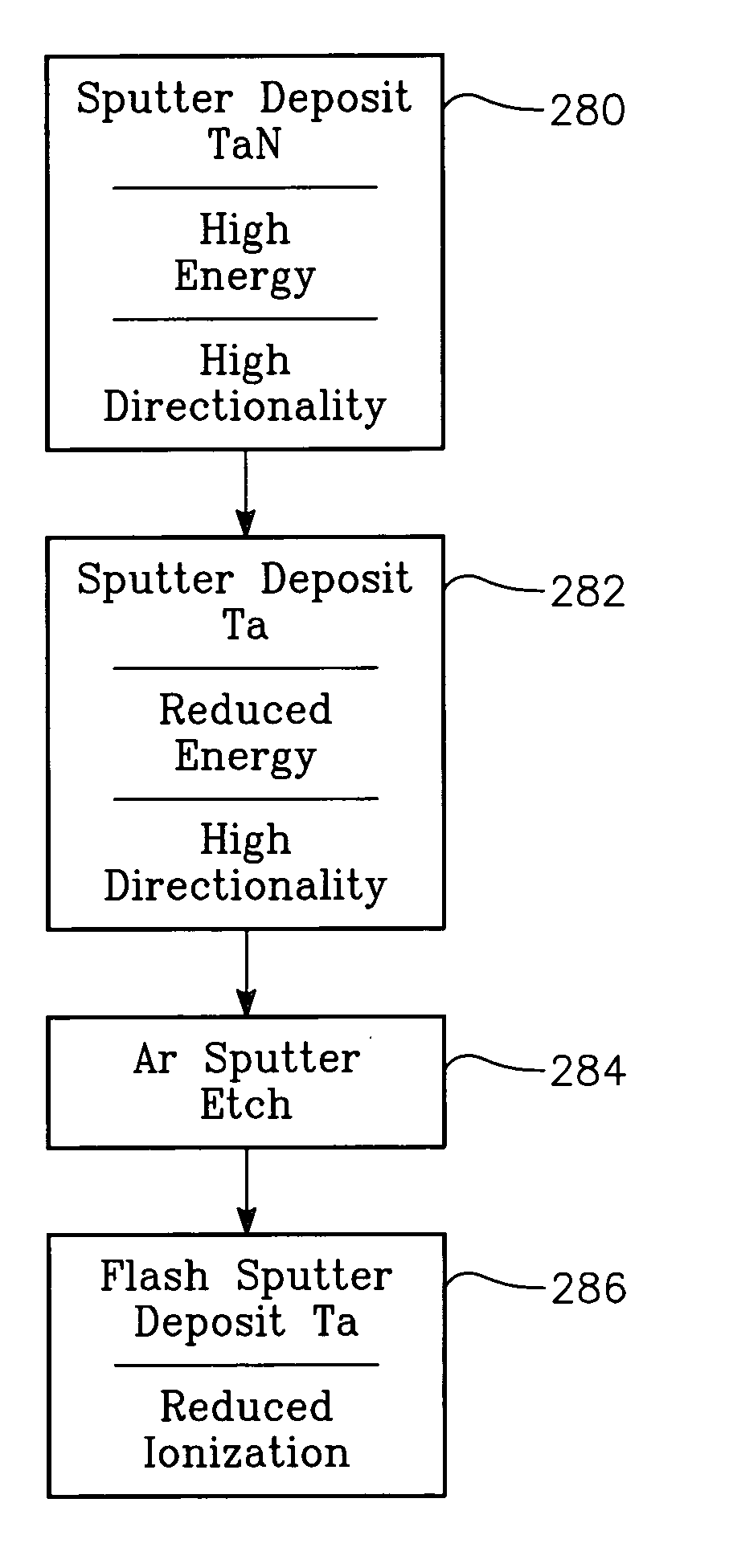
Multi-step process for forming a metal barrier in a sputter reactor
a metal barrier and sputter reactor technology, applied in the direction of vacuum evaporation coating, electrolysis components, coatings, etc., can solve the problem that the bias optimization alone has the difficulty of relatively narrow process window, and the sputter tantalum flux has a large horizontal velocity component towards the wafer center, so as to reduce the stray magnetic field, and enhance the effect of magnetic shielding
- Summary
- Abstract
- Description
- Claims
- Application Information
AI Technical Summary
Benefits of technology
Problems solved by technology
Method used
Image

Examples
Embodiment Construction
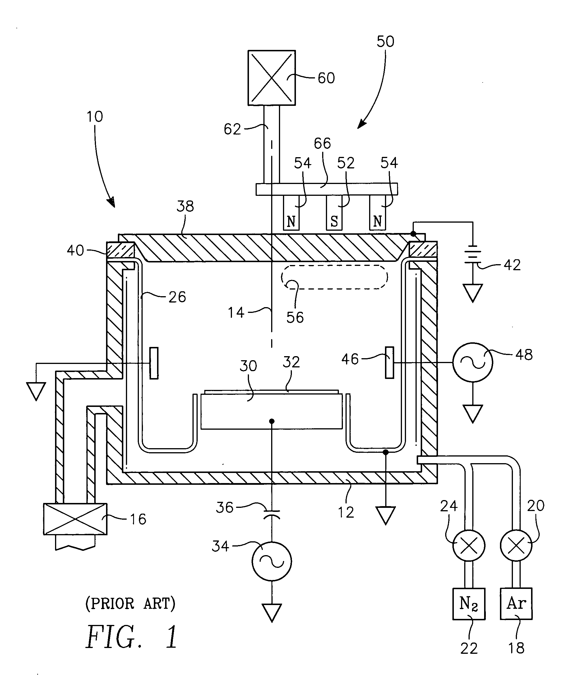
[0040] One aspect of the invention relies upon multiple solenoid coils or electromagnets, preferably arranged in an array, to flexibly tailor the magnetic field within the sputter chamber in multiple steps of a sputter and etch process enabled by the invention. A plasma reactor 70 illustrated schematically in cross section in FIG. 8 includes a quadruple electromagnet array 72 positioned generally in back of the RF coil 46. The quadruple electromagnet array 72 includes four solenoidal coils 74, 76, 78, 80 wrapped generally circularly symmetrically about the central axis 14 of the reactor 70. The coils 74, 76, 78, 80 are preferably arranged in a two-dimensional array extending around the central axis. The nomenclature is adopted of the top inner magnet (TIM) 74, top outer magnet (TOM) 76, bottom inner magnet (BIM) 78, and bottom outer magnet (BOM) 80. The coils 74, 76, 78, 80 may each be separately powered, for example, by respective variable DC current supplies 82, 84, 86, 88, prefer...
PUM
| Property | Measurement | Unit |
|---|---|---|
| Fraction | aaaaa | aaaaa |
| Time | aaaaa | aaaaa |
| Power | aaaaa | aaaaa |
Abstract
Description
Claims
Application Information