Light emitting diode

a light-emitting diode and diode technology, applied in the direction of semiconductor devices, semiconductor/solid-state device details, electrical apparatus, etc., can solve the problem of difficult control of narrow light directivity, and achieve the effect of preventing light scattering and obtaining more efficiently

Inactive Publication Date: 2005-12-01
CITIZEN ELECTRONICS CO LTD
View PDF5 Cites 17 Cited by
  • Summary
  • Abstract
  • Description
  • Claims
  • Application Information

AI Technical Summary

Benefits of technology

[0014] With this invention, since the light emitted from the side surfaces of the light emitting element does not strike the lower end of the reflection cup, light scattering can be prevented. Thus upward parallel rays of light can be extracted more efficiently. The light emitting diode therefore has a desired narrow directivity.

Problems solved by technology

When the light emitted from the light emitting face 11 of the light emitting element 3a strikes the inner circumferential edge 9 at the lower end of the reflection cup 4a, the light is scattered, rendering the control of narrow light directivity difficult.
The above problem is also experienced when the reflection cup 4a is formed by press-forming a metal material.

Method used


Image

  • Light emitting diode
  • Light emitting diode
  • Light emitting diode

Examples


Embodiment Construction

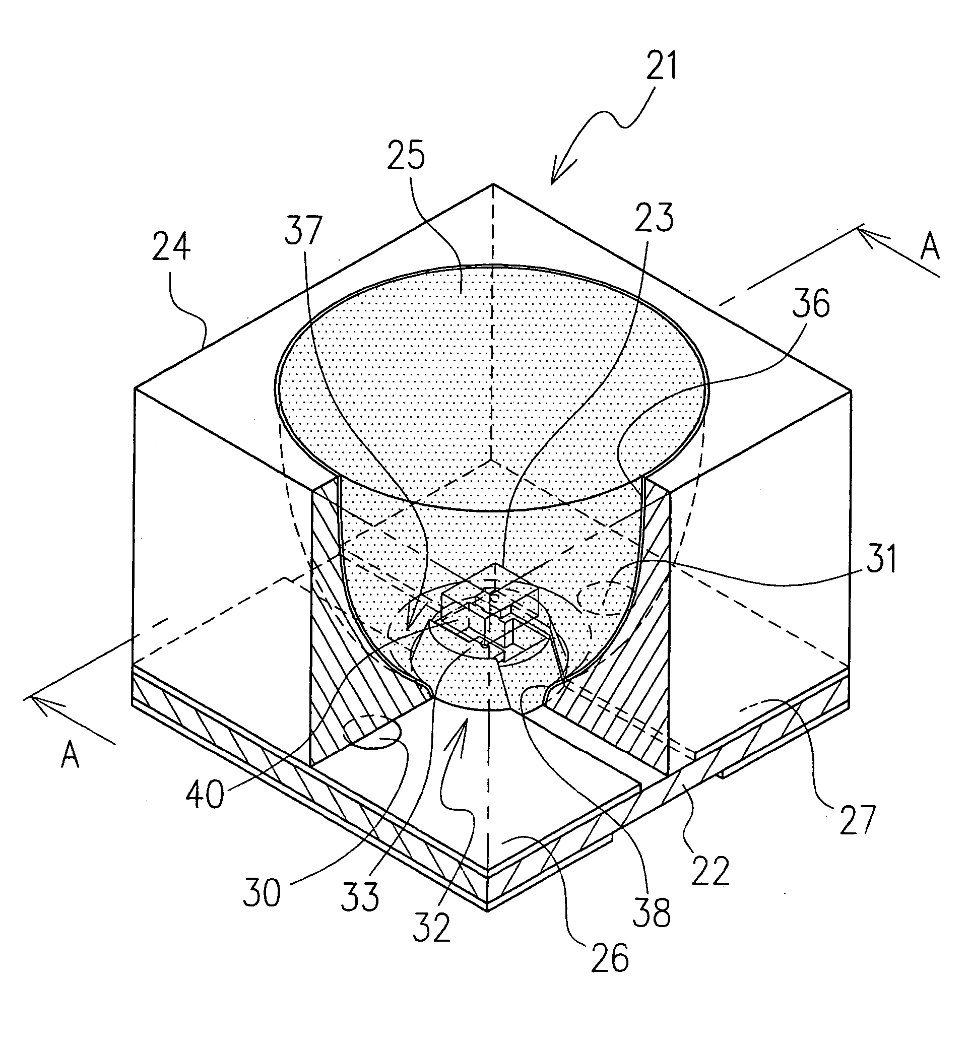
[0021] Now, one embodiment of the light emitting diode according to the present invention will be described in detail by referring to the accompanying drawings. FIG. 4 is a perspective view showing an overall construction of the light emitting diode as one embodiment of the invention. FIG. 5 is a cross-sectional view taken along the line A-A of FIG. 4. FIG. 6 is an enlarged view of a part B in FIG. 5.

[0022] As shown in FIG. 4 to FIG. 6, a light emitting diode 21 of this invention comprises, for example, an almost square base substrate 22 having a predetermined electrode pattern formed on a surface of a flexible substrate, a light emitting element 23 disposed at an almost central part of an upper surface of the base substrate 22, a reflection cup 24 arranged to surround the light emitting element 23 to control a directivity of light emitted from the light emitting element 23, and a light transmitting resin sealant 25 filled in the reflection cup 24.

[0023] The electrode pattern form...


PUM


Abstract

A light emitting diode of this invention comprises: a base substrate having a pair of electrode portions; a light emitting element mounted on the base substrate and electrically connected to the electrode portions; a reflection cup placed on the base substrate to surround the light emitting element; and a resin sealant sealing the light emitting element; wherein the base substrate is formed with a raised portion on an upper surface thereof and the light emitting element is placed on a top surface of the raised portion so that side surfaces of the light emitting element are situated higher than a lower end of the reflection cup. With this construction, light emitted from the side surfaces of the light emitting element can be extracted efficiently in an upward direction.

Description

CROSS REFERENCE TO RELATED APPLICATION [0001] The application claims the priority benefit of Japanese Patent Application No. 2003-344096, filed on Oct. 2, 2003, the entire description of which is incorporated herein by reference. BACKGROUND OF THE INVENTION [0002] 1. Field of the Invention [0003] The present invention relates to a light emitting diode used for illuminating a variety of electronic devices and also in recent years for illuminating panel meters of automobiles, and in particular, relates to a light emitting diode provided with a reflection cup to give an illuminating light a desired directivity. [0004] 2. Description of Related Art [0005] An example of light emitting diode of this kind is disclosed in Japanese Patent Disclosure No. 2002-324917. This light emitting diode, as shown in FIG. 1, comprises a base substrate 2 surface-mounted on a mother board 1, a light emitting element 3 put on an upper surface of the base substrate 2, a reflection cup 4 arranged to surround ...

Claims


Application Information

Patent Timeline
Patent Type & Authority Applications(United States)
IPC IPC(8): H01L23/00H01L29/22H01L33/48H01L33/56H01L33/60
CPCH01L33/486H01L33/60H01L33/62H01L2224/48091H01L2224/73265H01L2924/00012
Inventor ISODA, HIROTO
Owner CITIZEN ELECTRONICS CO LTD
Why Eureka
Try Eureka