Photoreceptor for electrophotography and electrophotography device having the same

a photoreceptor and electrophotography technology, applied in electrographic processes, instruments, coatings, etc., can solve problems such as difficult uniform dispersibility of filler, troublesome color balance and reproducibility, and shorten the life of the photoreceptor, so as to improve mechanical strength, reduce wear loss of the photoreceptor surface, and achieve stable and long-lasting favorable images

Inactive Publication Date: 2018-09-27
FUJI ELECTRIC CO LTD
View PDF1 Cites 2 Cited by
  • Summary
  • Abstract
  • Description
  • Claims
  • Application Information

AI Technical Summary

Benefits of technology

[0024]It has been revealed that by allowing a photosensitive layer to have the above-described specific charge transport layer composition, it is possible to reduce the wear loss of a photoreceptor surface while maintaining electrophotographic characteristics of a photoreceptor, thereby stably obtaining favorable images for long time, and it is also possible to improve mechanical strength according to the aspects of the present invention described above. This is thought to be because when a combination of a charge transport material, a resin binder, and a silane coupling surface treatment filler, which have uniform compatibility, is mixed in a charge transport layer, a filler contained in the layer is uniformly dispersed so that durability against abrasion due to external force applied to the photosensitive layer is improved, light permeability of the layer is also improved, and exposure light scattering is prevented, which eventually makes it possible to provide a high-quality photoreceptor having abrasion resistance and excellent image quality characteristics.

Problems solved by technology

Further, when paper dust or an external additive remains on the blade, there may be a case in which the photoreceptor surface is damaged, which results in shortened life of the photoreceptor.
In this regard, there may be a case in which abrasion of the photoreceptor surface is promoted, and it causes a potential fluctuation or sensitivity change, which results in an image abnormality, and thus, troubles occur in color balance and reproducibility in a color electrophotography device.
However, in a method of dispersing a filler in a layer, it is difficult to uniformly disperse the filler.
Further, the presence of an aggregate of the filler, decreased permeability of the layer, or scattering of exposure light via a filler might cause nonuniform charge transport or charge generation, resulting in deterioration of image characteristics.
Furthermore, although there is a method of adding a dispersing agent to improve the dispersibility of the filler, in this case, the dispersing agent itself affects photoreceptor characteristics, and, therefore, it is difficult to achieve satisfactory filler dispersibility and photoreceptor characteristics in a well-balanced manner.
However, the effects of these techniques are not sufficient, and therefore, the development of a photoreceptor for electrophotography that can achieve printing durability, repetition stability, and high resolution has been awaited.
In the technology disclosed in the above Patent Documents, the relationship among the respective components of the surface layer is not sufficiently examined, and it has been impossible to stably and favorably ensure electrical properties and image characteristics while sufficiently reducing the wear loss of the photoreceptor surface.

Method used


Image

  • Photoreceptor for electrophotography and electrophotography device having the same
  • Photoreceptor for electrophotography and electrophotography device having the same

Examples


example 1

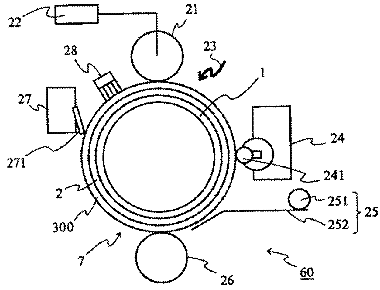
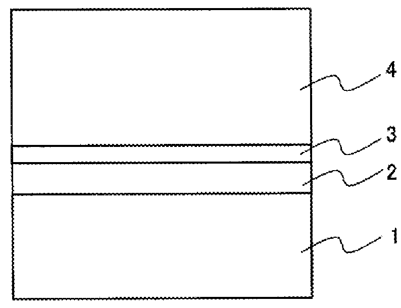
[0063]In 90 parts by mass of methanol, 5 parts by mass of alcohol-soluble nylon (trade name: “CM8000” manufactured by Toray Industries, Inc.) and 5 parts by mass of aminosilane-treated titanium oxide fine particles were dissolved and dispersed, thereby preparing a coating liquid 1. The outer periphery of an aluminum-made cylinder serving as a conductive substrate 1 having an outer diameter of 30 mm was dip-coated with the coating liquid 1 and dried at a temperature of 100° C. for 30 minutes, thereby forming an undercoat layer 2 having a film thickness of 3 μm.

[0064]Next, 1 part by mass of Y type titanyl phthalocyanine serving as a charge generation material and 1.5 parts by mass of a polyvinyl butyral resin (trade name: “S-LEC BM-2” manufactured by Sekisui Chemical Co., Ltd.) serving as a resin binder were dissolved and dispersed in 60 parts by mass of dichloromethane, thereby preparing a coating liquid 2. The above-described undercoat layer 2 was dip-coated with the coating liquid ...

example 2

[0067]A photoreceptor was produced in the same manner as in Example 1 except that the resin binder (B1) represented by structural formula (II-1) used in Example 1 was changed to a resin binder (B2) represented by the following structural formula (II-2):

example 3

[0068]A photoreceptor was produced in the same manner as in Example 1 except that the resin binder (B1) represented by structural formula (II-1) was used in Example 1 was changed to a resin binder (B3) represented by the following structural formula (II-3):


PUM

PropertyMeasurementUnit
particle sizeaaaaaaaaaa
number average primary particle diameteraaaaaaaaaa
chargeaaaaaaaaaa

Abstract

A photoreceptor for electrophotography and an electrophotography device having the same reduces wear loss of the photoreceptor surface and stably obtaining a favorable image for long time. The photoreceptor for electrophotography includes a conductive substrate and a charge transport layer provided on the conductive substrate. The charge transport layer contains a charge transport material, a resin binder, and an inorganic oxide filler surface-treated with a silane coupling agent. A difference (ΔSPa) in a dipole-dipole force component that is a Hansen solubility parameter between the charge transport material and the silane coupling agent satisfies a relationship ΔSPa<1.0. A difference (ΔSPb) in a London dispersion force component that is a Hansen solubility parameter between the resin binder and the silane coupling agent satisfies a relationship ΔSPb<2.5.

Description

CROSS-REFERENCE TO RELATED APPLICATIONS[0001]This non-provisional application is a continuation of International Application No. PCT / JP2017 / 014684 filed on Apr. 10, 2017, which claims priority from Japanese Patent Application No. 2016-130870 filed on Jun. 30, 2016, the entire contents of both of which are incorporated herein by reference.BACKGROUND OF THE INVENTION1. Field of the Invention[0002]The present invention relates to the improvement of a photoreceptor for electrophotography (hereinafter also simply referred to as “photoreceptor”) and an electrophotography device having the same, which are used for electrophotographic printers, copying machines, fax machines, and the like.2. Background of the Related Art[0003]A photoreceptor for electrophotography has a basic structure in which a photosensitive layer having a photoconductive function is disposed on a conductive substrate.In recent years, regarding organic photoreceptors for electrophotography containing an organic compound ...

Claims


Application Information

Patent Timeline
Patent Type & Authority Applications(United States)
IPC IPC(8): G03G5/05G03G5/047G03G5/10G03G5/06
CPCG03G5/0507G03G5/047G03G5/0564G03G5/102G03G5/0696G03G5/0525G03G5/0546G03G2215/00957G03G5/0629G03G5/142G03G5/061443G03G5/061473G03G5/05G03G5/06G03G5/14
Inventor HASEGAWA, TOMOKISUZUKI, SHINJIROZHU, FENGQIANGKOBAYASHI, HIROTAKA
Owner FUJI ELECTRIC CO LTD
Why Eureka
Try Eureka