Liquid crystal display device and driving method thereof

Inactive Publication Date: 2005-12-01
HITACHI DISPLAYS
View PDF3 Cites 16 Cited by
  • Summary
  • Abstract
  • Description
  • Claims
  • Application Information

AI Technical Summary

Benefits of technology

[0018] A brief explanation of advantageous effects obtained by the present invention disclosed in this specification is as follows. According to the liquid crystal display device and the driving method of the present invention, it is possible to

Problems solved by technology

However, in the technique disclosed in the above-mentioned patent literature, to set the gate line to “H” after the given time A lapses

Method used


Image

  • Liquid crystal display device and driving method thereof
  • Liquid crystal display device and driving method thereof
  • Liquid crystal display device and driving method thereof

Examples


Example

[0036] Hereinafter, various embodiments of the present invention will be explained in detail in conjunction with the attached drawings.

[0037] Here, in all of the drawings, parts having identical functions are indicated by the same symbols, and a repeated explanation thereof is omitted.

(Basic Constitution of TFT Type Liquid Crystal Display Module to Which the Present Invention is Applied)

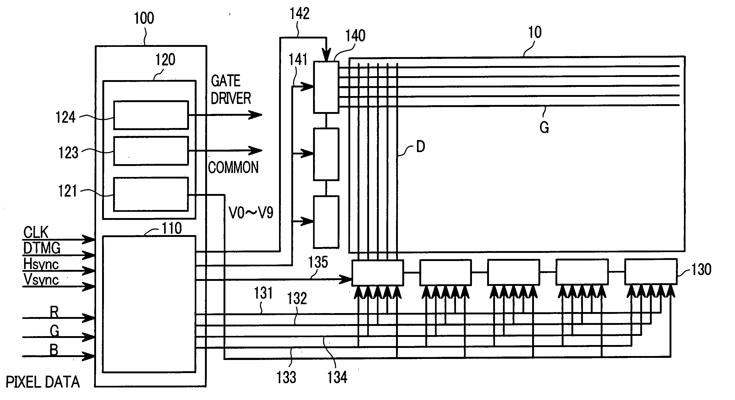
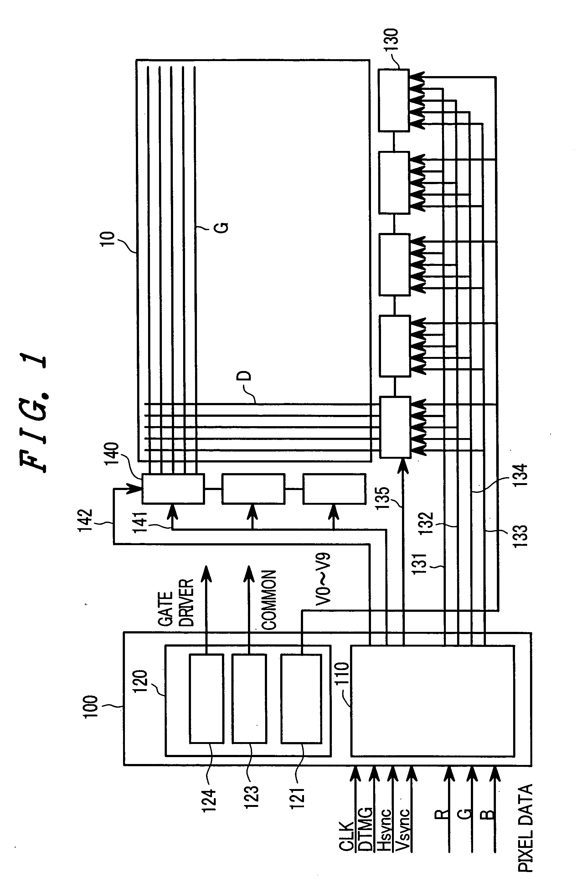
[0038]FIG. 1 is a block diagram showing the constitution of a liquid crystal display module to which the present invention is applied.

[0039] In the liquid crystal display module shown in FIG. 1, a drain driver 130 is arranged on a long side of a liquid crystal display panel 10, while a gate driver 140 is arranged on a short side of the liquid crystal display panel 10. The drain driver 130 and the gate driver 140 are directly mounted on peripheral portions of one glass substrate (for example, a TFT substrate) of the liquid crystal display panel 10.

[0040] An interface part 100 is mounted on an in...


PUM


Abstract

A liquid crystal display device can have enhanced display quality of a display screen by preventing the generation of lateral stripes on the display screen when the polarity of a gray scale voltage is inverted for every N (N≧2) lines without providing a new display control signal. In the liquid crystal display device, a gray scale voltage is applied to a plurality of pixels, and the polarity of the gray scale voltage is inverted for every N (N≧2) video lines. The polarity inversion line position at which the polarity of the gray scale voltage is changed from the positive polarity to the negative polarity or vice versa different among respective frames. Thus, the polarity inversion line position is discontinuous among continuous frames. Further, the positive polarity gray scale voltage and the negative polarity gray scale voltage are supplied to the respective pixels every N/2 times.

Description

BACKGROUND OF THE INVENTION [0001] The present invention relates in general to a liquid crystal display device and to a driving method thereof, and, more particularly, the invention relates to a technique which is effective when applied to an N line inversion driving method in which the polarity of a gray scale voltage applied to pixels is inverted for every plural lines. [0002] An active matrix type liquid crystal display device, in which switching of active elements, such as thin film transistors (TFT), is carried out to produce a display, has been popularly used as a display device in a personal computer or the like. [0003] In general, with respect to a liquid crystal layer, when the same voltage (the DC voltage) is applied to the liquid crystal layer for a long time, the inclination of the liquid crystal layer becomes fixed, and, hence, an image detention phenomenon is induced, thus shortening the lifetime of the liquid crystal layer. [0004] To prevent such a drawback, in a liqu...

Claims


Application Information

Patent Timeline
IPC IPC(8): G09G3/20G02F1/133G09G3/36
CPCG09G3/3614G09G2320/0204G09G2310/0289G09G3/3688
Inventor NAKAMURA, MASASHITAKEDA, NOBUHIRO
Owner HITACHI DISPLAYS
Why Eureka
Try Eureka