Method and apparatus for servo writing in a disk drive

Inactive Publication Date: 2005-12-01
KK TOSHIBA
View PDF8 Cites 20 Cited by
  • Summary
  • Abstract
  • Description
  • Claims
  • Application Information

AI Technical Summary

Benefits of technology

[0014] In accordance with) an aspect of the present invention, there is provided a servo writing method, which can preven

Problems solved by technology

As a result, this is a factor of generating a servo data area having worsened recording quality.
However, the bi-directional servo writing method has the following problems.
More specifically, several-track servo data having worsened recordin

Method used


Image

  • Method and apparatus for servo writing in a disk drive
  • Method and apparatus for servo writing in a disk drive
  • Method and apparatus for servo writing in a disk drive

Examples


Embodiment Construction

[0029] Embodiments of the present invention will be described below with reference to the accompanying drawings.

[0030] (Structure of Disk Drive)

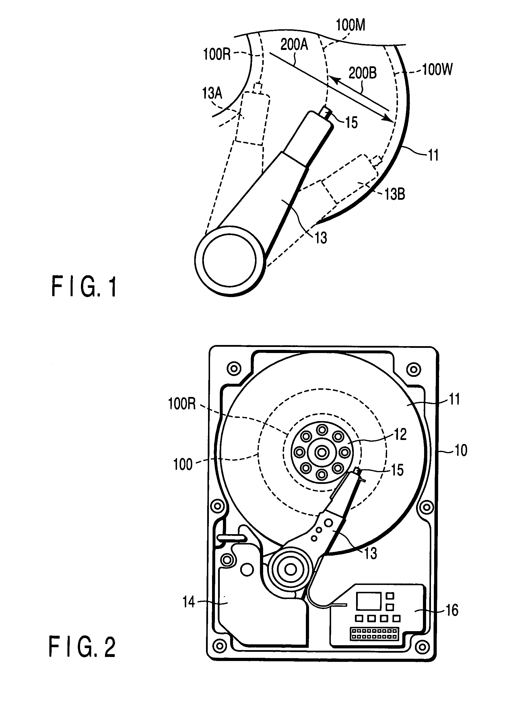
[0031] As shown in FIG. 2, a disk drive of this embodiment has the structure in which disk medium 11, rotary actuator 13 and circuit board 16 are built to a drive cover 10. The disk drive of this embodiment is configured considering a state that servo data 100 is fully recorded in a servo writing process using a self-servo writing method described later before product delivery or a state before recorded.

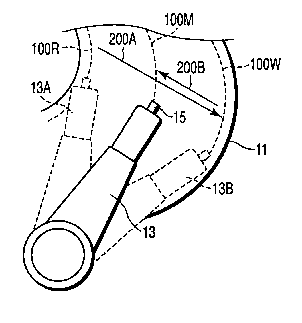
[0032] The disk medium 11 is rotated at high speed by a spindle motor 12. The disk medium 11 is a perpendicular magnetic recordable medium. Before the disk medium 11 is built to the drive cover 10, reference servo data (or called as seed servo data) 100R is previously recorded to the innermost circumferential area on the disk.

[0033] The rotary actuator 13 is attached with a magnetic head (hereinafter referred simply to as head) 15 at the ...


PUM


Abstract

In a self-servo writing method, servo data is re-recorded, and thereby, servo data having worsened recording quality is rewritten. According to the method, the servo data is recorded in an entire range on a disk medium, and thereafter, the servo write direction is switched to re-record the servo data in a range to an intermediate circumferential area on the disk medium. In this way, the servo data is re-recorded to correct servo data having worsened recording quality.

Description

CROSS-REFERENCE TO RELATED APPLICATIONS [0001] This application is based upon and claims the benefit of priority from prior Japanese Patent Application No. 2004-162085, filed May 31, 2004, the entire contents of which are incorporated herein by reference. BACKGROUND OF THE INVENTION [0002] 1. Field of the Invention [0003] The present invention relates to a self-servo writing method of a disk drive. In particular, the present invention relates to a self-servo writing method applied to a perpendicular magnetic recording disk drive. [0004] 2. Description of the Related Art [0005] In recent years, a rotary actuator rotating radially on a disk medium has been used in a disk drive such as hard disk drive. The tip end portion of the rotary actuator is attached with a magnetic head. The magnetic head has a write head (recording device) and a read head (reproduce device), which are mounted in a separated state. [0006] Offsets equivalent to several tens of tracks exist between the write and r...

Claims


Application Information

Patent Timeline
IPC IPC(8): G11B21/10G11B5/596G11B21/02
CPCG11B5/59655
Inventor YANO, KOJIOSAFUNE, KOJI
Owner KK TOSHIBA
Why Eureka
Try Eureka