Wireless device authentication at mutual reduced transmit power

a wireless device and transmit power technology, applied in the field of wireless network communications, can solve the problems of eavesdropping devices' inability to intercept authentication, and achieve the effect of reducing power operations, facilitating selection of a particular network, and reducing transmit power

Inactive Publication Date: 2005-12-01
AVAGO TECH INT SALES PTE LTD
View PDF1 Cites 21 Cited by
  • Summary
  • Abstract
  • Description
  • Claims
  • Application Information

AI Technical Summary

Benefits of technology

[0010] Operation according to the present invention enables wireless devices to select and join a particular wireless network with minimal user interaction and with ease in selection of the network. According to the present invention, after selection of a network and request for admission to the network, reduced power operations are performed during corresponding authentication operations. Reduced power authentication operations ensure that admission to the selected network is attempted and not with a different network. Further, the reduced power operations minimize the ability of eavesdropping devices to intercept authentication information
[0012] Using this operating technique, a user of a wireless device having a minimal (or no) user interface, e.g., a wireless headset, may easily select a particular network. With the master device and the new device reducing their transmit power during the joining operations, joining a desired network is substantially guaranteed. Further, with the reduced power operations of the present invention, minimal user input is required for the joining operations. Moreover, when multiple networks are present, e.g., a scatternet, the user of the new device may easily select a desired network from a plurality of networks having overlapping coverage area.

Problems solved by technology

Further, the reduced power operations minimize the ability of eavesdropping devices to intercept authentication information

Method used


Image

  • Wireless device authentication at mutual reduced transmit power
  • Wireless device authentication at mutual reduced transmit power
  • Wireless device authentication at mutual reduced transmit power

Examples


Embodiment Construction

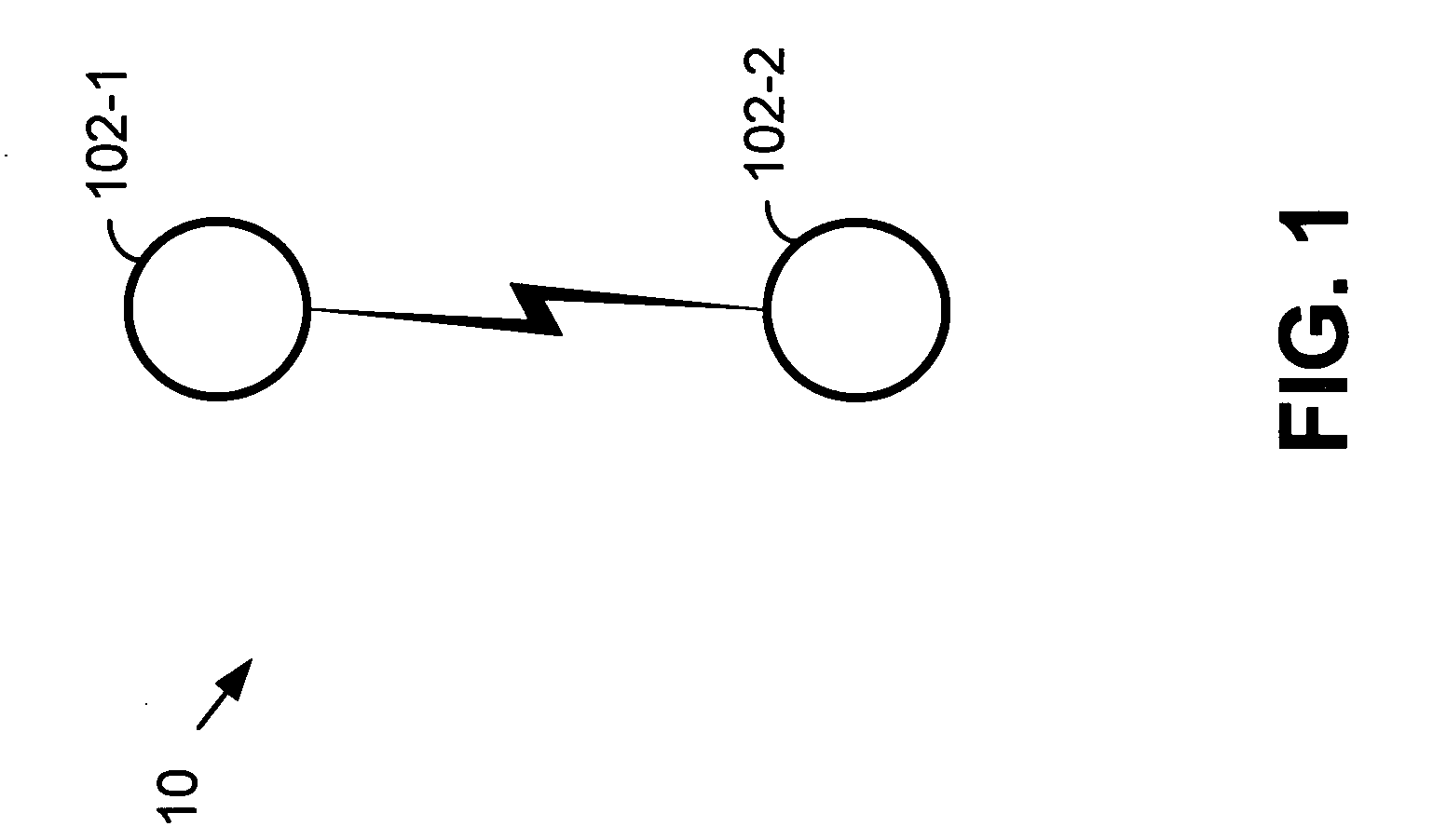
[0020]FIG. 1 illustrates a network 10 that includes two wireless devices 102-1 and 102-2. Network 10 is, for example, a wireless Bluetooth point-to-point piconet where wireless device 102-1 is a master Bluetooth system and wireless device 102-2 is a slave Bluetooth system, where the master 102-1 and slave 102-2 share the same channel. The point-to-point network 10 described with reference to FIG. 1 need not include Bluetooth devices 102-1, 102-2, but, rather, may comprise any type of wireless device. These wireless devices 102-1 and 102-2 may include digital computers, computer peripherals such as printers, scanners, mice, keyboards, etc., personal data assistants (PDAs), wireless telephones, wireless headsets, and other wireless devices.

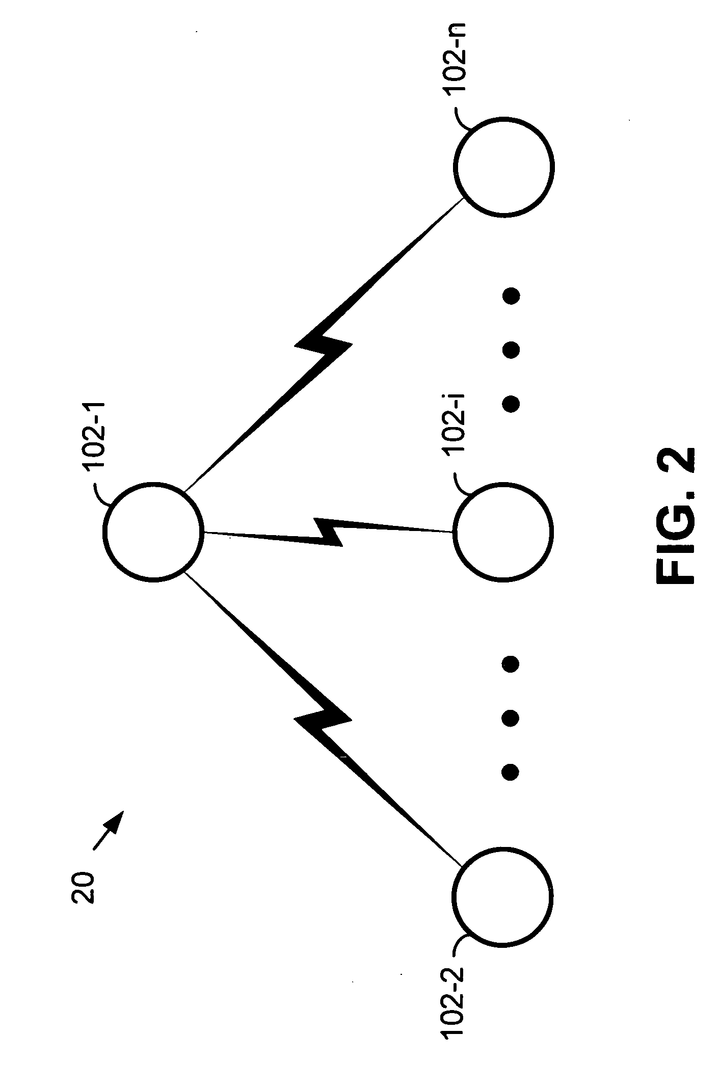
[0021]FIG. 2 illustrates a network 20 that includes a plurality of wireless devices 102-1, 102-2 . . . 102-i . . . 102-n (2≦i≦n). Wireless network 20 is, for example, a point-to-multipoint Bluetooth piconet where wireless device 102-1 is a master B...


PUM


Abstract

A system and method for facilitating the authentication of wireless devices in an environment with multiple wireless networks. A user wishing to join an operating wireless network can bring his wireless device within close physical proximity, for example, less than one meter, of a device in the network that he wishes to join. The user then presses an authenticate button, which causes both devices to enter a low transmission power mode. In such case, the devices are only capable of operation within the close proximity. Being in low power mode will diminish the possibility of eavesdropping on the authentication process. Power down mode also reduces the amount of message traffic in the area and saves scarce power and processing resources at the nodes, which are now out of range. Authentication then takes place in low power mode and once completed, both devices resume normal power levels and continue communicating normally.

Description

CROSS REFERENCE TO PRIORITY APPLICATION [0001] This application claims priority to U.S. Provisional Patent Application No. 60 / 264,993 filed Jan. 30, 2001, which is incorporated herein by reference in its entirety.FIELD OF THE INVENTION [0002] The present invention relates to wireless communications; and more particularly to wireless network communications. BACKGROUND OF THE INVENTION [0003] The number and popularity of wireless communications devices in use continues to rise rapidly all over the world. Not only are mobile phones very popular, but there is also a demand for wireless networking devices. One standard for wireless networking, which has been widely accepted, is the Specification of the Bluetooth System, v. 1.0 (“Bluetooth Specification”). The Bluetooth Specification continues to evolve and subsequent versions are expected to be available. [0004] The Bluetooth Specification enables the creation of small personal area networks (PAN's), where the typical operating range of ...

Claims


Application Information

Patent Timeline
Patent Type & Authority Applications(United States)
IPC IPC(8): H04B7/005H04L12/56H04L29/06
CPCH04L63/0492H04L63/08H04L63/104H04L63/1475H04W12/06Y02B60/50H04W52/283H04W52/50H04W76/02H04W84/18H04W12/12H04W76/10
Inventor OLSON, ERLENDMURPHY, K.C.
Owner AVAGO TECH INT SALES PTE LTD
Why Eureka
Try Eureka