Radio base station apparatus and radio communication method

Inactive Publication Date: 2005-12-01
FUJITSU LTD
View PDF50 Cites 74 Cited by
  • Summary
  • Abstract
  • Description
  • Claims
  • Application Information

AI Technical Summary

Benefits of technology

[0023] According to this invention, immediately after the downlink communication channel for transmitting data to the user equipment is switched, the directivity of transmission power is controlled using the directivity information calculated before this switching. Therefore, even immediately after the communication channel is switched, a transmission beam with appropriate directivity can be quickly formed.
[0024] According to the present

Problems solved by technology

Furthermore, when signals are uniformly transmitted in all directions in a sector, the number of reflection wa

Method used


Image

  • Radio base station apparatus and radio communication method
  • Radio base station apparatus and radio communication method
  • Radio base station apparatus and radio communication method

Examples


Embodiment Construction

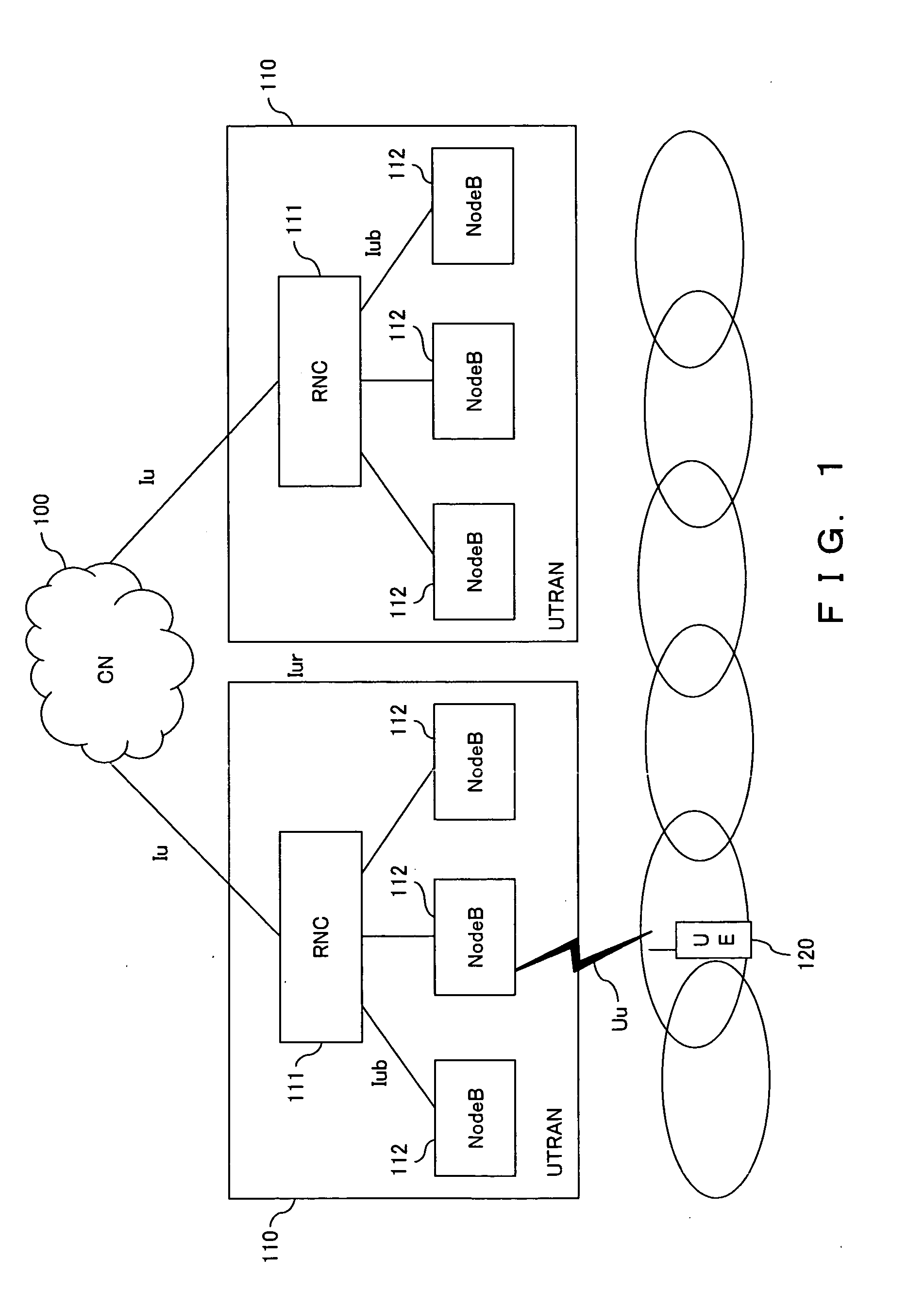
[0048] The following is the explanation of the embodiments of the present invention in reference to the accompanying drawings. The present invention is not limited to the 3GPP system. In this specification, however, the embodiments applied to the system shown in FIG. 1 are explained.

[0049] In the 3GPP system of the embodiment, as shown in FIG. 7, a high speed shared control channel (HS-SCCH), an HS-physical downlink shared channel (HS-PDSCH) and an HS-dedicated physical control channel (HS-DPCCH) are set on Uu interface between a radio base station (NodeB) 10 and the user equipment (UE) 120 as a radio channel used for high speed downlink packet access (HSDPA).

[0050] Both the high speed physical downlink shared channel HS-PDSCH and high speed shared control channel HS-SCCH are shared channels in a downlink direction (that is, the direction from the radio base station 10 to the user equipment 120). Here, the high speed physical downlink shared channel HS-PDSCH mainly transmits user ...


PUM


Abstract

The radio base station apparatus comprises: a plurality of antenna elements for transmitting and receiving radio signals; a detection unit for detecting information about an uplink dedicated channel corresponding to a first user equipment from signals received via the plurality of antenna elements; a directivity control unit for determining directivity of transmission power based on the information detected by the detection unit when signals are transmitted to the first user equipment via the downlink shared channel; and a transmission unit for transmitting signals with the directivity determined by the directivity control unit.

Description

BACKGROUND OF THE INVENTION [0001] 1. Field of the Invention [0002] The present invention relates to an apparatus for transmitting a radio signal and especially relates to a radio base station apparatus for implementing signal transmission having directivity using an adaptive array antenna. [0003] 2. Description of the Related Art [0004] At present, the operation of standardizing the third generation mobile communications system has been pursed in the 3rd Generation Partnership Project (3GPP). [0005]FIG. 1 is a block diagram of a network related to the 3GPP system. The 3GPP system comprises an upper level network (core network (CN)) 100, a radio access network (UTRAN: UMTS (Universal Mobile Telecommunications System) terrestrial radio access network) 110 and a mobile station (user equipment (UE)) 120. Here, each radio access network 110 is provided with a radio network controller (RNC) 111 and a plurality of radio base stations (NodeBs) 112. [0006] The interface between the radio ba...

Claims


Application Information

Patent Timeline
IPC IPC(8): H04B1/707H04B7/06H04B7/08H04B7/26H04J13/00H04W16/28H04W72/04H04W88/08
CPCH04B7/086H04B7/0617
Inventor HARA, MASAYUKISHINOZAKI, ATSUSHI
Owner FUJITSU LTD
Why Eureka
Try Eureka