Ceramic honeycomb filter and its production method

a honeycomb filter and honeycomb technology, applied in the field of honeycomb filter, can solve the problems of high exhaust gas temperature, adversely affecting human beings and the environment, and less burning pm in the usual diesel engine operation, and achieve the effect of easy continuous regeneration and high pm-capture efficiency

Active Publication Date: 2013-03-05
HITACHI METALS LTD
View PDF38 Cites 63 Cited by
  • Summary
  • Abstract
  • Description
  • Claims
  • Application Information

AI Technical Summary

Benefits of technology

[0012]Accordingly, an object of the present invention is to provide an easy-to-produce honeycomb filter, which is easy to conduct continuous regeneration, and has high PM-capturing efficiency in an early stage.DISCLOSURE OF THE INVENTION
[0013]As a result of intensive research in view of the above object, the inventors have found that the above problems can be solved not by forming the same fine pore structures as PM layers, but by forming structures in penetrating holes in the cell walls, such that the captured PM is easily accumulated on the structures to rapidly form the PM layers. The present invention has been completed based on such finding.

Problems solved by technology

When such exhaust gas is released into the air, it may adversely affect human beings and the environment.
As PM continues to be captured by the cell walls 2, the penetrating holes on and in the cell walls are clogged by PM, resulting in pressure loss increase when the exhaust gas passes through the honeycomb filter.
However, as high exhaust gas temperatures as burning PM are less obtained in a usual diesel engine operation.
In an operation state where exhaust gas temperatures are so low that the above continuous regeneration cannot be conducted (catalysts are not activated), PM is accumulated on the cell wall surfaces and in the penetrating holes in the cell walls, resulting in the increased pressure loss of the honeycomb filter.
Although the extension of the time period T can be achieved by reducing the pressure loss of the honeycomb filter by increasing the volume and average diameter of pores in the cell walls, such method causes decrease in initial PM-capturing efficiency during the period A in the figure.
However, when PM does not easily enter pores in the cell walls, it is less brought into contact with catalysts in the pores, resulting in insufficient effect of accelerating the burning of PM.
As a result, continuous regeneration is not conducted even at exhaust gas temperatures at which the catalysts are activated, so that pressure loss increases in a short period of time by PM accumulated on the cell wall surfaces, frequently needing the forced regeneration.
It describes that the fine pore structures should be as thin as 3.5 μm or less to reduce pressure loss, but it is extremely difficult to form fine pore structures as thin as 3.5 μm or less with substantially spherical fine particles.
Although the fine pore structures can be formed by using fibrous fine particles, the fibrous fine particles are harmful to humans, thus difficult to handle in the production process.
However, because the coating of the heat-resistant material is conducted by dipping, pores opening at the cell wall surfaces are clogged to have smaller diameters, and heat-resistant particles are attached to inner surfaces of pores in the cell walls to reduce pore diameters, resulting in pressure loss increase.

Method used


Image

  • Ceramic honeycomb filter and its production method
  • Ceramic honeycomb filter and its production method
  • Ceramic honeycomb filter and its production method

Examples


example 1

Production of Honeycomb Filter

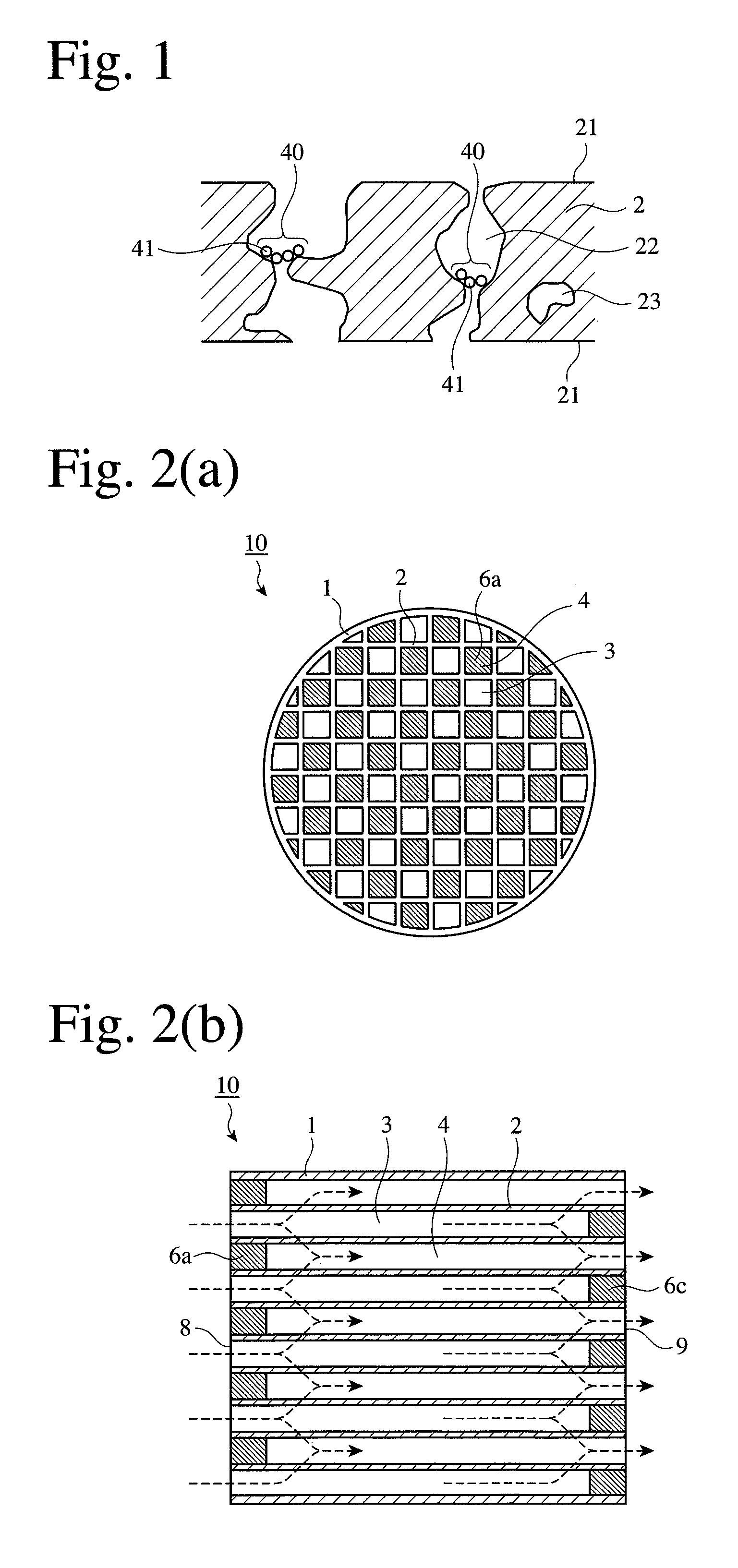
[0044]To produce the honeycomb filter 10 shown in FIG. 2 by a known method, kaolin powder, talc powder, silica powder, alumina powder and aluminum hydroxide powder were mixed to prepare cordierite-forming material powder comprising 50% by mass of SiO2, 35% by mass of Al2O3 and 15% by mass of MgO. The amounts of these components may be adjusted in a range of 48-52% for SiO2, 33-37% for Al2O3 and 12-15% for MgO. This powder was mixed with methylcellulose and hydroxypropyl methylcellulose as binders, a lubricant, and a foamed resin as pore formers. After thorough dry-blending, water was added to carry out sufficient kneading to prepare a moldable ceramic material. This moldable material was extrusion-molded and cut to a honeycomb-structure, molded article. This molded article was dried and sintered to produce a cordierite honeycomb structure. This honeycomb structure was provided with plugs 6a, 6c in end portions of flow paths 3, 4 to obtain the honeycomb ...

examples 10 and 11

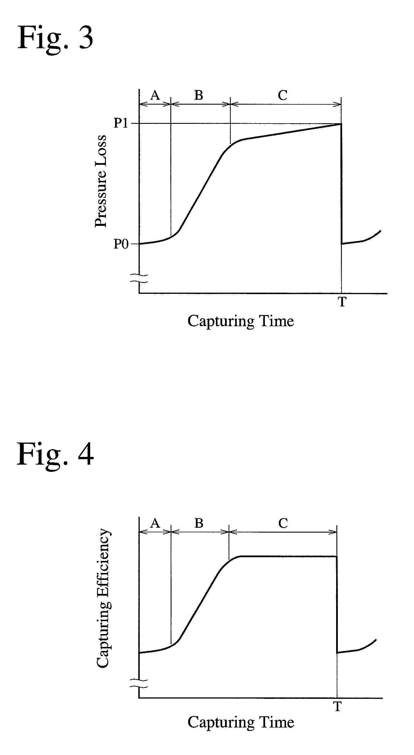
[0068]The honeycomb filter of Example 10 was produced in the same manner as in Example 1, except that the entire honeycomb filter was immersed in water before heat-resistant particles were supplied thereto together with air through the exhaust-gas-inlet-side end 8. The honeycomb filter of Example 11 was produced in the same manner as in Example 10, except that only half of the honeycomb filter on the exhaust-gas-inlet side was immersed in water. With respect to these honeycomb filters, an average pore diameter, porosity, an opening area ratio of pores, mass difference between the downstream side and the upstream side, initial pressure loss (expressed by a relative value assuming that Example 1 was 100), capturing efficiency, and (pressure loss 4 h / pressure loss 2 h) were measured in the same manner as in Example 1. The results are shown in Table 3. The honeycomb filters of Examples 10 and 11 had improved capturing efficiency than that of Example 1, though their initial pressure loss...


PUM

PropertyMeasurementUnit
pore diameteraaaaaaaaaa
diameteraaaaaaaaaa
diameteraaaaaaaaaa

Abstract

A ceramic honeycomb filter comprising a honeycomb structure having large numbers of flow paths partitioned by porous cell walls, and plugs alternately formed in the flow paths on the exhaust-gas-inlet and outlet sides, the area ratio of pores opening at the cell wall surfaces being 20% or more, porous, cross-linked structures being formed by heat-resistant particles introduced together with a gas into penetrating holes constituted by communicating pores in the cell walls, such that they clog the penetrating holes, and the cross-linked structures being formed more on the exhaust-gas-outlet side of the ceramic honeycomb filter than on the exhaust-gas-inlet side.

Description

CROSS REFERENCE TO RELATED APPLICATIONS[0001]This application is a National Stage of International Application No. PCT / JP2007 / 073212 filed Nov. 30, 2007, claiming priority based on Japanese Patent Application No. 2006-324981 filed Nov. 30, 3006, the contents of all of which are incorporated herein by reference in their entirety.FIELD OF THE INVENTION[0002]The present invention relates to a ceramic honeycomb filter used for capturing particulate matter in an exhaust gas discharged from diesel engines, etc. to clean the exhaust gas, and its production method.BACKGROUND OF THE INVENTION[0003]An exhaust gas emitted from diesel engines contains PM (particulate matter) based on carbonaceous soot and SOF (soluble organic fraction) of high-boiling-point hydrocarbons. When such exhaust gas is released into the air, it may adversely affect human beings and the environment. For this reason, a PM-capturing ceramic honeycomb filter, which may be called “honeycomb filter” in short, has been dispo...

Claims


Application Information

Patent Timeline
Patent Type & Authority Patents(United States)
IPC IPC(8): B01D39/14B01D50/00B01D24/00B01D39/06F01N3/00
CPCB01D39/2093C04B41/4545C04B41/009F01N3/0222C04B41/87C04B35/00C04B38/0006C04B35/195C04B35/565C04B35/478C04B41/457C04B41/5024C04B41/5059C04B41/5041Y02T10/20C04B2111/00793Y02T10/12
Inventor ISHIZAWA, TOSHITAKA
Owner HITACHI METALS LTD
Why Eureka
Try Eureka