Gearless one way drive

a one-way drive and gearless technology, applied in the direction of wrenches, screwdrivers, manufacturing tools, etc., can solve the problems of less tolerant devices to dirt or corrosion, and achieve the effect of reducing the overall height of the complete instant gearless drive, facilitating the use of instant gearless drives, and reducing the size of the head portion

Inactive Publication Date: 2005-12-08
SMART TOOLD LTD
View PDF26 Cites 12 Cited by
  • Summary
  • Abstract
  • Description
  • Claims
  • Application Information

AI Technical Summary

Benefits of technology

[0017] In an alternative embodiment the aperture in the flexible head is preferably circular for engaging a circular drive means, such as a cylindrical spigot on a fastener socket drive. This provides an instant gearless drive version of a conventional ratchet bar, which will grip the spigot instantly when the handle is turned in the drive direction, yet will move relative to the spigot when the handle is turned towards a reposition direction. When increasing torque is applied in a drive direction (clockwise or counterclockwise) to the handle the action of the mechanism is such as to increase the locking action as more torque is applied.
[0029] When the handle portion is operated in a reverse or reposition direction the degree of clamping between the inner ring surface and the drive means is substantially decreased enabling the flexible ring to rotate, reverse or reposition relative to the drive means. Simultaneously, the resilient cam of the first embodiment is further compressed against the base of the clamping shoe. The strength of the resilient spring pressure exerted on the resilient cam is carefully chosen to prevent, as far as possible, any play between the drive portion, clamping shoe, head portion, handle portion and axis pin, yet not enough to prevent the clamping or locking action of the clamping shoe upon the drive portion being overcome allowing free movement in the reverse or reposition direction.

Problems solved by technology

The increasing intricacies of the ratchet mechanisms have also resulted in devices less tolerant to dirt or corrosion.

Method used


Image

  • Gearless one way drive
  • Gearless one way drive
  • Gearless one way drive

Examples


Embodiment Construction

[0042] The embodiments of the present invention will now be described with reference to the drawings. In the various embodiments and corresponding drawings like reference numerals will be used to indicate like features throughout.

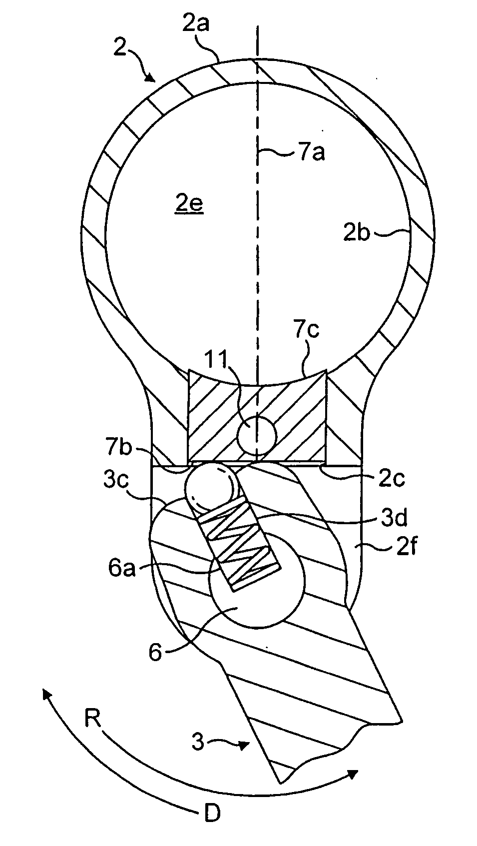
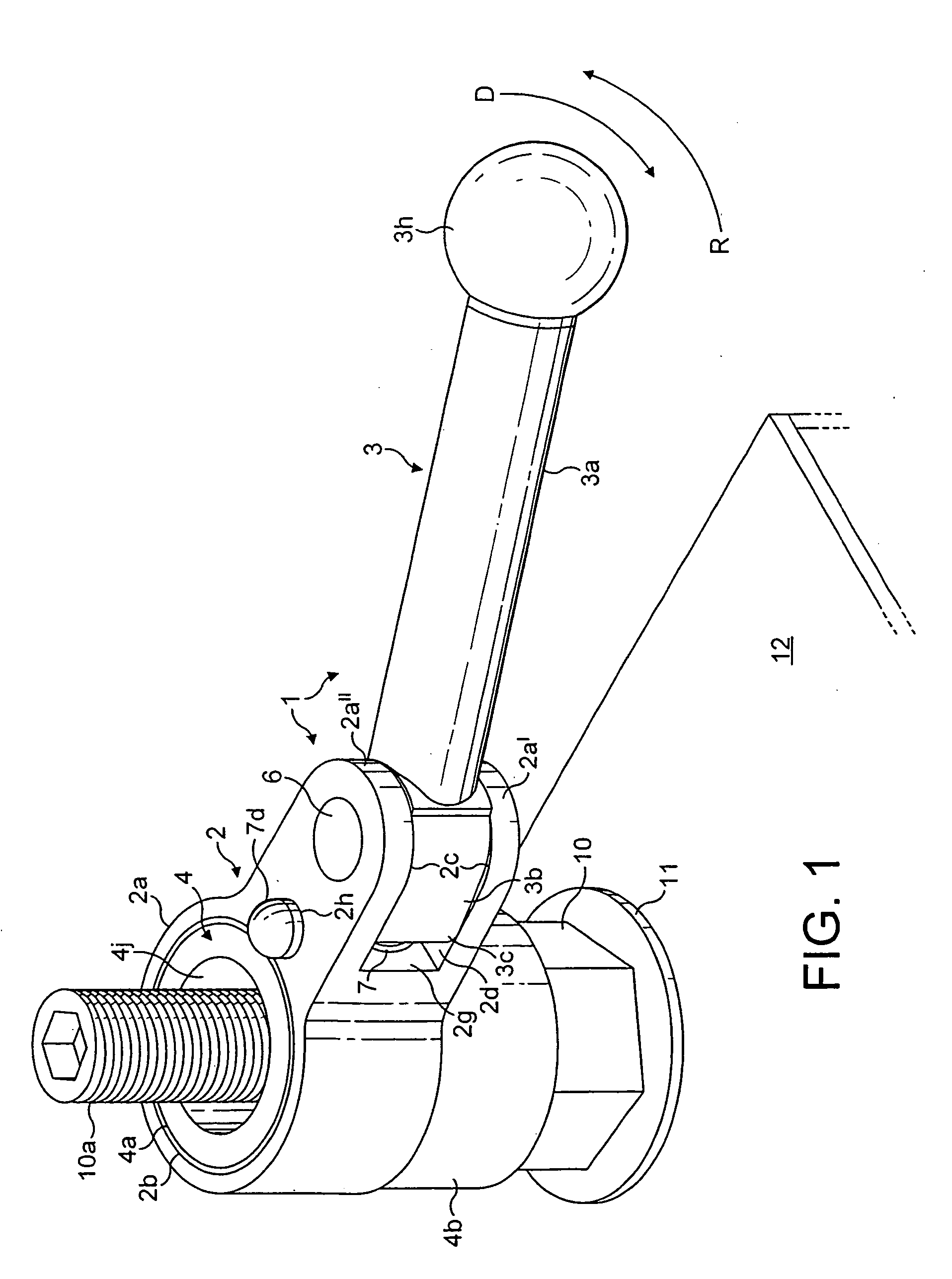
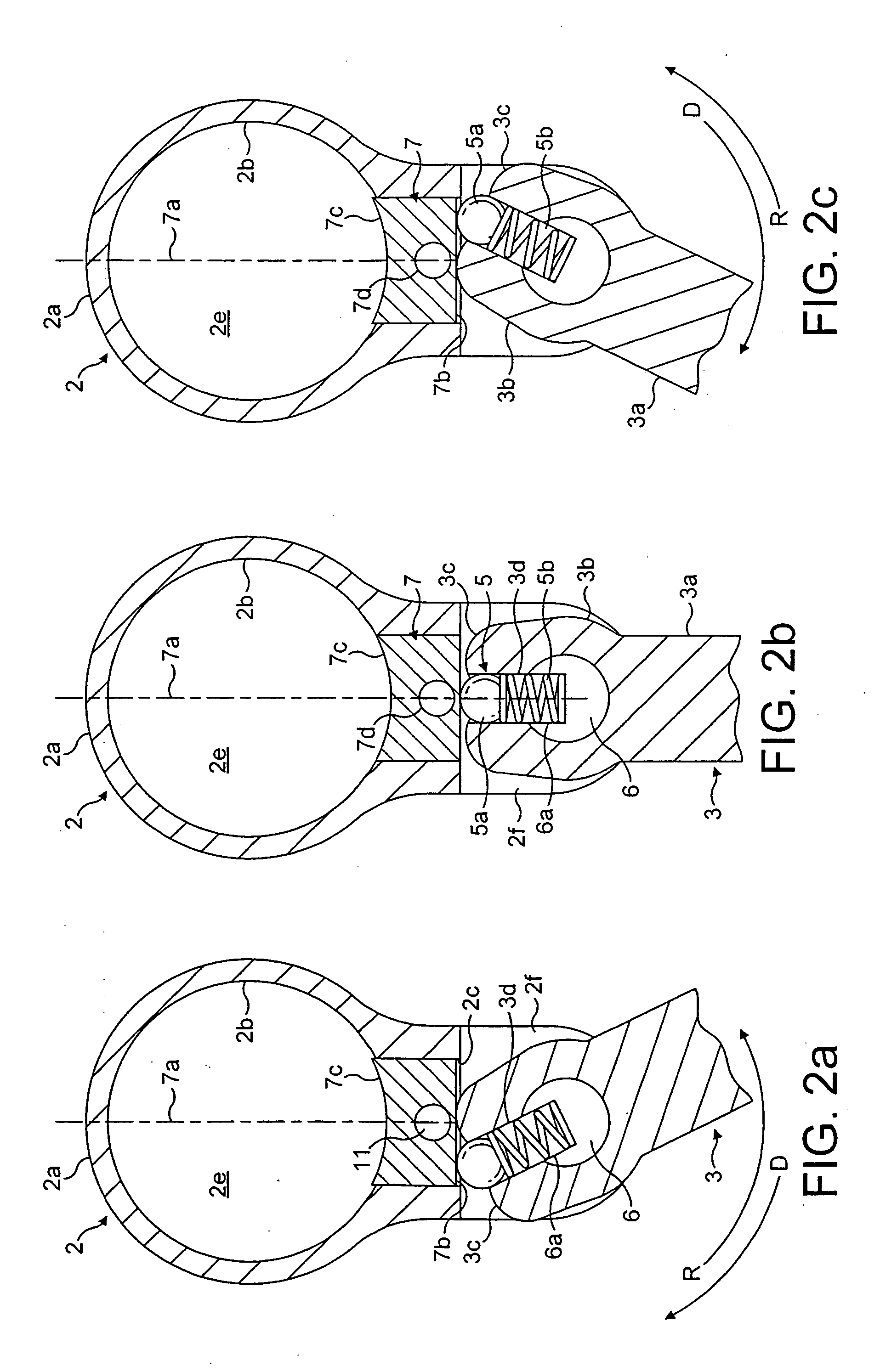
[0043] Referring to the drawings and in particular FIGS. 1 to 3, an instant gearless drive (1) comprises a head portion (2) and a handle portion (3) movable one relative to the other, both parts being formed of steel, for example. The head portion includes a flexible ring (2a) having an inner cylindrical ring surface (2b) and a shoe slot (2c). Flat planar spaced parallel arms (2a′) and (2a″) extend radially outward from the flexible ring (2a). The handle portion (3) is mechanically connected by an axis pin (6) through the arms (2a′) and (2a″) to the head portion (2) and projects into the space (2f) between arms (2a′) and (2a″) of the head portion.

[0044] The handle portion (3) comprises a lever end (3a), and an opposed levered end (3b) located between arms...


PUM


Abstract

A head portion (2) and handle portion (3) pivot about an axis pin (6). The head portion (2) is first biased in the required drive direction (D) bias being sustained by a resilient cam (5) being to one side of a clamping shoe (7) centre line (7a). When torque is applied in the drive direction (D) to a levered end (3a) of the handle portion the resultant force acts through the pertinent cam (3c) on levered end (3b) of the handle portion forcing the clamping shoe (7) inwards locking the inner surface (2b) and clamping surface (7c) onto the drive portion (4) of a socket (8) or circular drive (9) in order to operate a fastener (10). A spring cam (5) takes up any play between the handle portion (3) head portion (2) axis pin (6) clamping shoe (7) and drive portion (4) yet compresses sufficiently to allow the instant gearless drive (1) relative to the drive portion (4) to be repositioned (R). The clamping shoe (7) is a sliding fit within the shoe slot (2c) can be conveniently operated against the resilient cam (5) by a release pin (11) within an appropriate slot (2e).

Description

FIELD OF THE INVENTION [0001] The present invention relates to a gearless drive having a one way locking operation and more particularly, though not exclusively, concerns a tool similar in operation to a ratchet tool having a ratchet bar. BACKGROUND OF THE INVENTION [0002] A ratchet bar tool may be used for applying torque via an attached square drive and appropriate socket to a nut, bolt or screw (hereinafter referred to as a fastener) for the purpose of tightening or slackening the fastener. The ratchet bar is movable relative to the socket in one direction only. Motion between the ratchet bar and the socket in the opposite direction is prevented by a set of angular teeth, which co-operate with a resilient pawl so as to create a locking motion in one direction only and free movement in the opposite direction. This operation of the socket and fastener via a ratchet bar is much more convenient in restrictive situations than the use of a fixed bar operated socket as there is seldom a...

Claims


Application Information

Patent Timeline
Patent Type & Authority Applications(United States)
IPC IPC(8): B25B13/18B25B13/46B25B13/52
CPCB25B13/46
Inventor BUCHANAN, NIGEL ALEXANDER
Owner SMART TOOLD LTD
Why Eureka
Try Eureka