
System for medical diagnosis

a medical diagnosis and system technology, applied in the field of medical diagnosis, can solve the problems of difficult to obtain supine, affecting the size of the system, and complicated arrangements required to position the detector head

Inactive Publication Date: 2005-12-08
IMAGING PET TECH
View PDF11 Cites 11 Cited by
  • Summary
  • Abstract
  • Description
  • Claims
  • Application Information

AI Technical Summary

Benefits of technology

[0007] It is an object of the present invention to provide a new system, which obviates or mitigates at least one of the disadvantages described above.
[0008] The system uses a mechanism that enables the detector head to rotate within the inner space of the gantry and enables the system to obtain desired images without moving up / down or tilting the detector head. The system enables a patient to be supported in different ways.
[0009] In accordance with an aspect of the present invention, there is provided a system which includes: a base; a gantry mounted on the base, the gantry having an annular support ring, which defines a cylindrical inner space, and a detector head for taking image, which is fixed to the inner surface of the annular support ring; a mechanism for allowing the annular support ring to rotate along a centre axis of the inner space and for preventing horizontal, vertical and angular movements of the annular support; and a bed system for supporting and adjustably positioning a patient at a location with respect to the detector head.

Problems solved by technology

While such systems have improved the quality of the images, complicated arrangements are required to position the detector head.
That affects the size of the system.
Further, it is difficult to obtain supine and prone imagines in conventional systems that have limited rotation of 180° and operate on the principle of raising and lowering the detector on a vertical column.

Method used


Image

  • System for medical diagnosis
  • System for medical diagnosis
  • System for medical diagnosis

Examples


Embodiment Construction

)

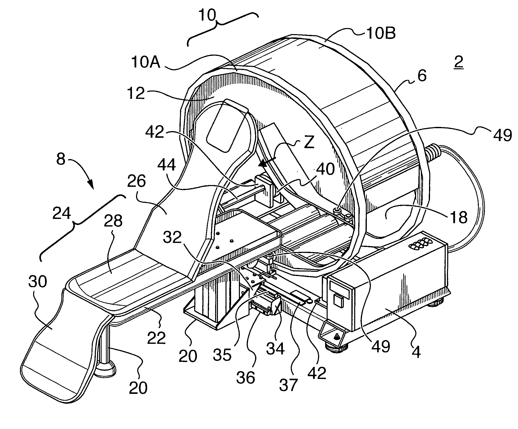
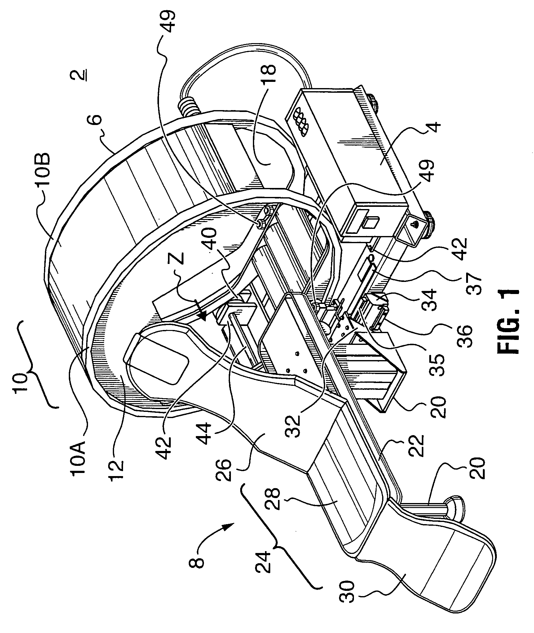
[0029]FIG. 1 shows a medical diagnosis system 2 in accordance with an embodiment of the present invention. The medical diagnosis system 2 includes a base 4, a gantry 6 for a medical nuclear camera and a patient bed system 8 for supporting and positioning a patient. The gantry 6 is mounted on the base 4, and has an annular support 10. The annular support 10 supports and guides a detector head 12 for the nuclear camera. The nuclear camera may be a scintillation camera or gamma camera, and may be a Cardiac Gamma Camera.

[0030] The base 4 has a fixing mechanism that enables the base 4 to be fixed on a flat plane (e.g. floor or wall) and a moving mechanism that enables the base 4 to move on the plane.

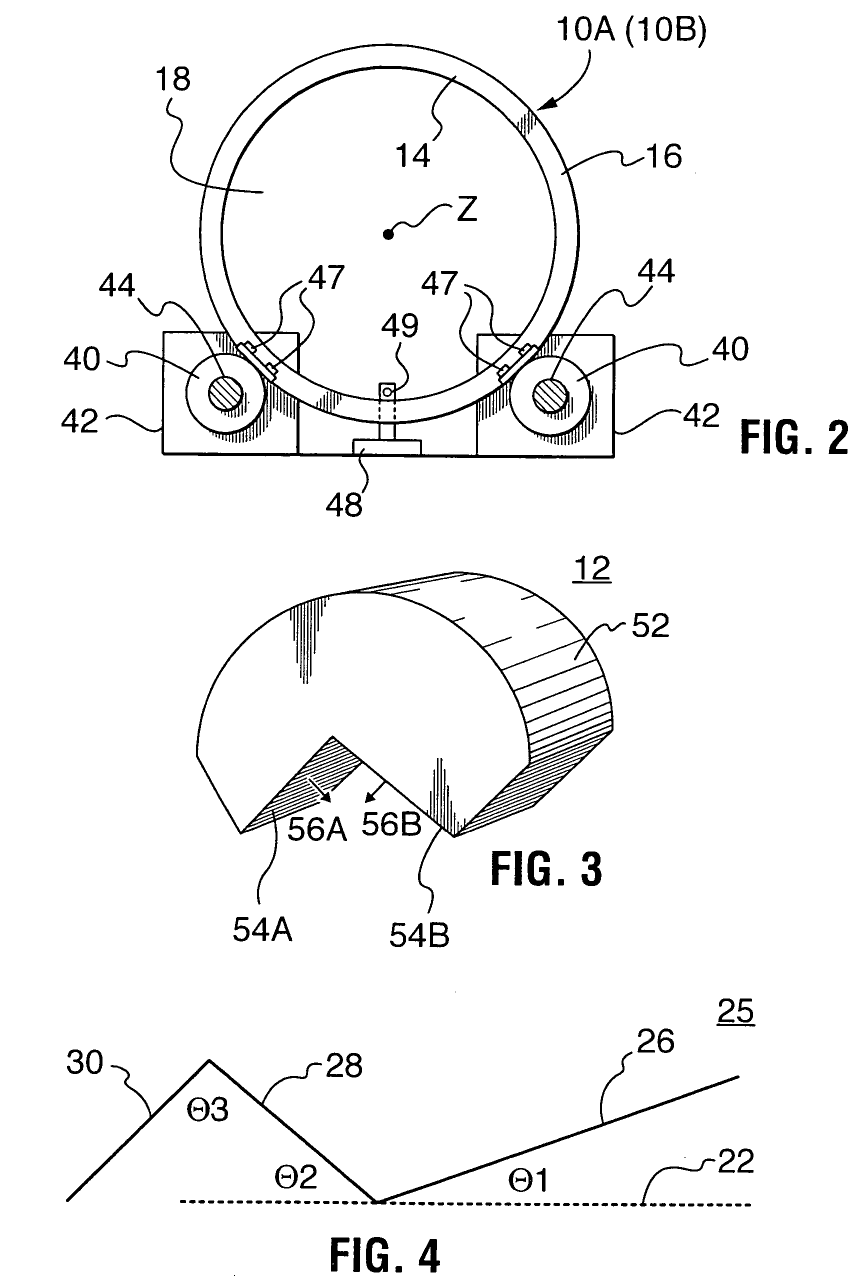
[0031] The annular support 10 has an inner surface (14 of FIG. 2) and an outer surface (16 of FIG. 2), and defines a cylindrical inner space 18. The detector head 12 is fused to the inner surface (14) of the annular support 10 so as to be positioned within the cylindrical inner space 18. A...


PUM


Abstract

A system for medical diagnosis is provided. The system includes a gantry mounted on the base. The gantry has an annular support, which defines a cylindrical inner space. A detector head is fixed to the inner surface of the annular support. The annular support rotates along an axis of the inner space and is prevented from moving in horizontal and vertical direction and moving angularly. The system has a patient bed system, which is detachably attached to the base, and has a contact surface for supporting the patient. Pivot mechanism(s) and adjustable arm(s) enable the contact surface to have a plurality of configurations.

Description

FIELD OF INVENTION [0001] The present invention relates to a system for medical diagnosis. BACKGROUND OF THE INVENTION [0002] Scintillation cameras are well known in the art of nuclear medicine, and are used for medical diagnostics. A patient ingests, inhales or is injected with a small quantity of a radioactive isotope. The radioactive isotope emits radiations that are detected by a scintillation medium in the scintillation camera. The scintillation medium is commonly a sodium iodide crystal, BGO or other. The scintillation medium emits a small flash or scintillation of light in response to stimulating radiation from a patient. The intensity of the scintillation light is proportional to the energy of the stimulating radiation, such as a gamma ray. [0003] A conventional system for a scintillation camera such as a gamma camera includes a detector head, which detects gamma rays emitted from a patient and converts is them into electrical signals and a processor for processing the signa...

Claims


Application Information

Patent Timeline
IPC IPC(8): A61B6/00A61B6/03A61B6/04G01T1/164
CPCA61B6/04A61B6/037
Inventor STARK, IAIN
Owner IMAGING PET TECH
Learn More