Residual accommodation threshold for correction of presbyopia and other presbyopia correction using patient data

a patient data and threshold technology, applied in the field of goal functions or visual function diagnostic metrics, can solve the problems of loss of near-distance focus ability, limited ability to change shape, and loss of elastic properties of crystalline lenses, so as to mitigate or treat presbyopia in a particular, improve near vision, and improve the effect of near vision

Inactive Publication Date: 2005-12-08
AMO MFG USA INC
View PDF32 Cites 54 Cited by
  • Summary
  • Abstract
  • Description
  • Claims
  • Application Information

AI Technical Summary

Benefits of technology

[0013] The present invention provides improved devices, systems, and methods for mitigating or treating presbyopia and other vision conditions. The present invention can establish a prescription that mitigates or treats presbyopia in a particular patient. In some embodiments, an optically optimized shape may be generated based on patient data input. Typically, the shape will represent a compromise between improved near vision and improved distance vision. These optimized shapes can be derived numerically using input patient parameters such as pupil size, residual accommodation, and desired vergence. Presbyopia-mitigating shapes may be scaled (or otherwise varied) in response to patient data such as one or more pupil diameters. Appropriate scaling may be determined at least in part from prior patient data from

Problems solved by technology

There may also be a loss in the ability to focus on objects at near distances.
By the age of 65 years, the crystalline lens has often lost almost all elastic properties and has only limited ability to change shape.
Unfortunately, with monovision the individual may not clearly see objects that are intermediately positioned because the object is out-of-focus for both eyes.
Also, an individual may have trouble seeing with only one eye, or may be unable to tolerate an imbalance between their eyes.
Problems remain with such techniques, however, such as inconsistent and unpredictable outcomes.
Many of these ablation profiles can provide a single excellent focus of the eye, yet they do not prov

Method used


Image

  • Residual accommodation threshold for correction of presbyopia and other presbyopia correction using patient data
  • Residual accommodation threshold for correction of presbyopia and other presbyopia correction using patient data
  • Residual accommodation threshold for correction of presbyopia and other presbyopia correction using patient data

Examples


Embodiment Construction

[0087] Although the methods, devices, and systems of the present invention are described primarily in the context of a laser eye surgery system, it should be understood that the techniques of the present invention may be adapted for use in other eye treatment procedures and systems such as contact lenses, intra-ocular lenses, radial keratotomy, collagenous corneal tissue thermal remodeling, removable corneal lens structures, glass spectacles, corneal ring implants, and the like.

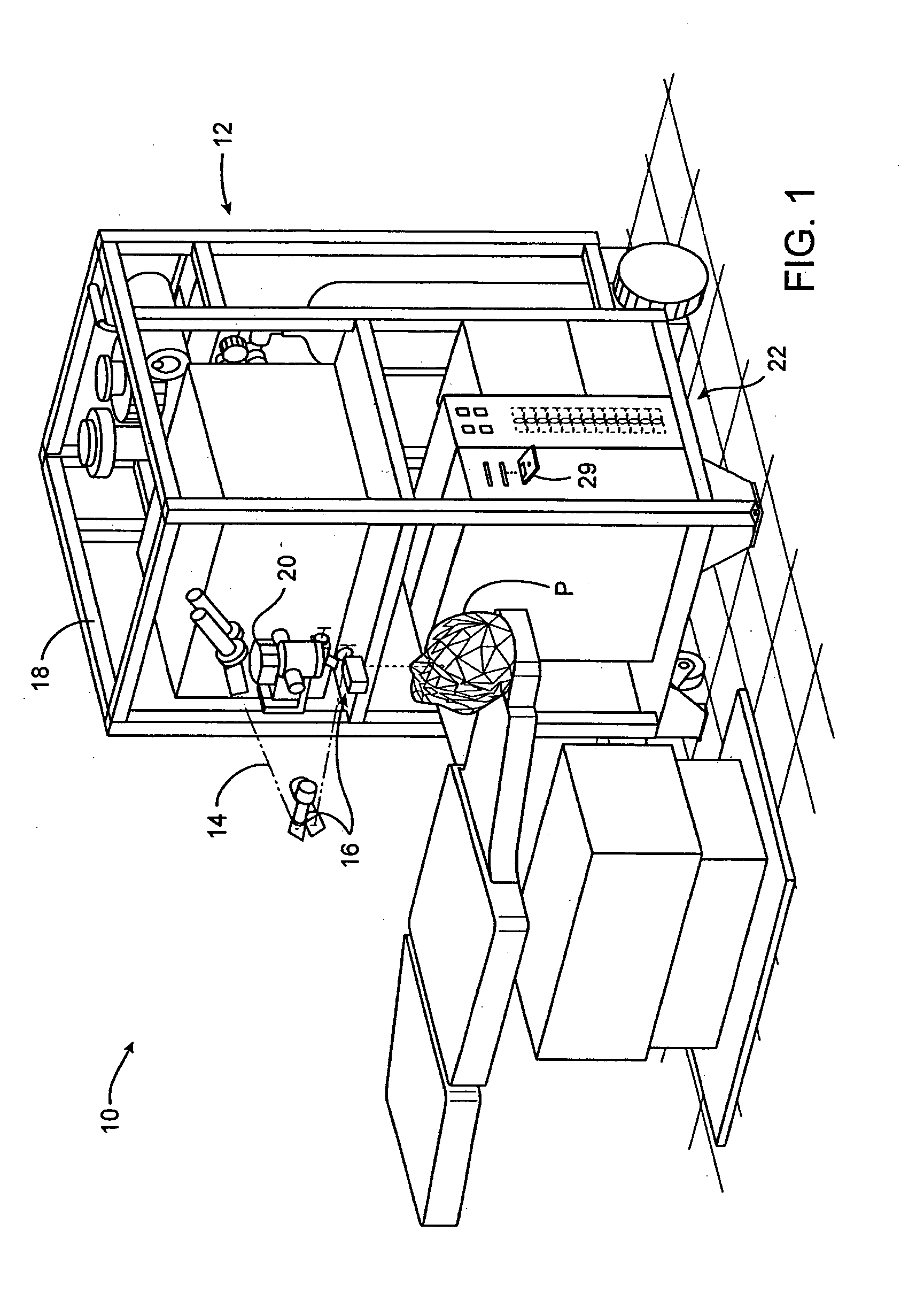
[0088] Turning now to the drawings, FIG. 1 illustrates a laser eye surgery system 10 of the present invention, including a laser 12 that produces a laser beam 14. Laser 12 is optically coupled to laser delivery optics 16, which directs laser beam 14 to an eye E of patient P. A delivery optics support structure (not shown here for clarity) extends from a frame 18 supporting laser 12. A microscope 20 is mounted on the delivery optics support structure, the microscope often being used to image a cornea of eye E...


PUM


Abstract

Methods, devices, and systems establish an optical surface shape that mitigates or treats presbyopia in a particular patient. The combination of distance vision and near vision in a patient can be improved, often based on input patient parameters such as pupil size, residual accommodation, and power need. Iterative optimization may generate a customized corrective optical shape for the patient. Threshold residual accommodation is established for presbyopia treatment.

Description

CROSS-REFERENCES TO RELATED APPLICATIONS [0001] The present application claims the benefit under 35 USC 119(e) from U.S. Patent Application No. 60 / 579,124 filed Jun. 10, 2004 (Attorney Docket No. 018158-022230US), and is a continuation-in-part of U.S. patent application Ser. No. 10 / 911,400 filed Aug. 3, 2004 (Attorney Docket No. 018158-022240 US), which is a continuation-in-part of U.S. patent application Ser. No. 10 / 738,358 filed Dec. 5, 2003 (Attorney Docket No. 018158-022220 US), which claims the benefit under 35 USC 119(e) from U.S. Patent Application Nos. 60 / 519,885 filed Nov. 13, 2003 (Attorney Docket No. 18158-022310); 60 / 468,387 filed May 5, 2003 (Attorney Docket No. 18158-022300); 60 / 468,303 filed May 5, 2003 (Attorney Docket No. 18158-022210); and 60 / 431,634 filed Dec. 6, 2002 (Attorney Docket No. 18158-022200), the entire disclosures of which are incorporated herein by reference for all purposes.STATEMENT AS TO RIGHTS TO INVENTIONS MADE UNDER FEDERALLY SPONSORED RESEARCH ...

Claims


Application Information

Patent Timeline
IPC IPC(8): A61B3/00A61B3/06A61B3/10A61B3/107A61B3/11G02C7/02
CPCA61F2009/00872A61B3/0025A61B3/09A61B3/112
Inventor DAI, GUANGMINGYEE, KINGMAN
Owner AMO MFG USA INC
Why Eureka
Try Eureka