Apparatus and method of encoding/decoding an audio signal

a technology of audio signal and audio signal, applied in the field of apparatus and method of encoding/decoding an audio signal, can solve the problems of increasing the importance of problems and the deterioration of the sound quality of the audio signal

Inactive Publication Date: 2005-12-08
SAMSUNG ELECTRONICS CO LTD
View PDF3 Cites 47 Cited by
  • Summary
  • Abstract
  • Description
  • Claims
  • Application Information

AI Technical Summary

Benefits of technology

[0011] Additional aspects of the present general inventive concept will be set forth in part in the description which follows and, in part, will be obvious from the description, or may be learned by practice of the general inventive concept.
[0017] The foregoing and / or other aspects of the present general inventive concept are also achieved by providing a computer readable medium having executable code to perform the audio encoding method.

Problems solved by technology

Due to this ERP-DRP resonance effect, even if high quality earphones, headphones, or phone ear pieces are used, there is a problem in that people hear an audio signal having a middle band that is largely amplified.
As a result, sound quality of the audio signal deteriorates.
In particular, this problem is becoming more important as the use of earphones, headphones, phone ear pieces, etc. increases along with the widespread use of portable audio devices and cell-phones.

Method used


Image

  • Apparatus and method of encoding/decoding an audio signal
  • Apparatus and method of encoding/decoding an audio signal
  • Apparatus and method of encoding/decoding an audio signal

Examples


Embodiment Construction

[0029] Reference will now be made in detail to the embodiments of the present general inventive concept, examples of which are illustrated in the accompanying drawings, wherein like reference numerals refer to the like elements throughout. The embodiments are described below in order to explain the present general inventive concept while referring to the figures.

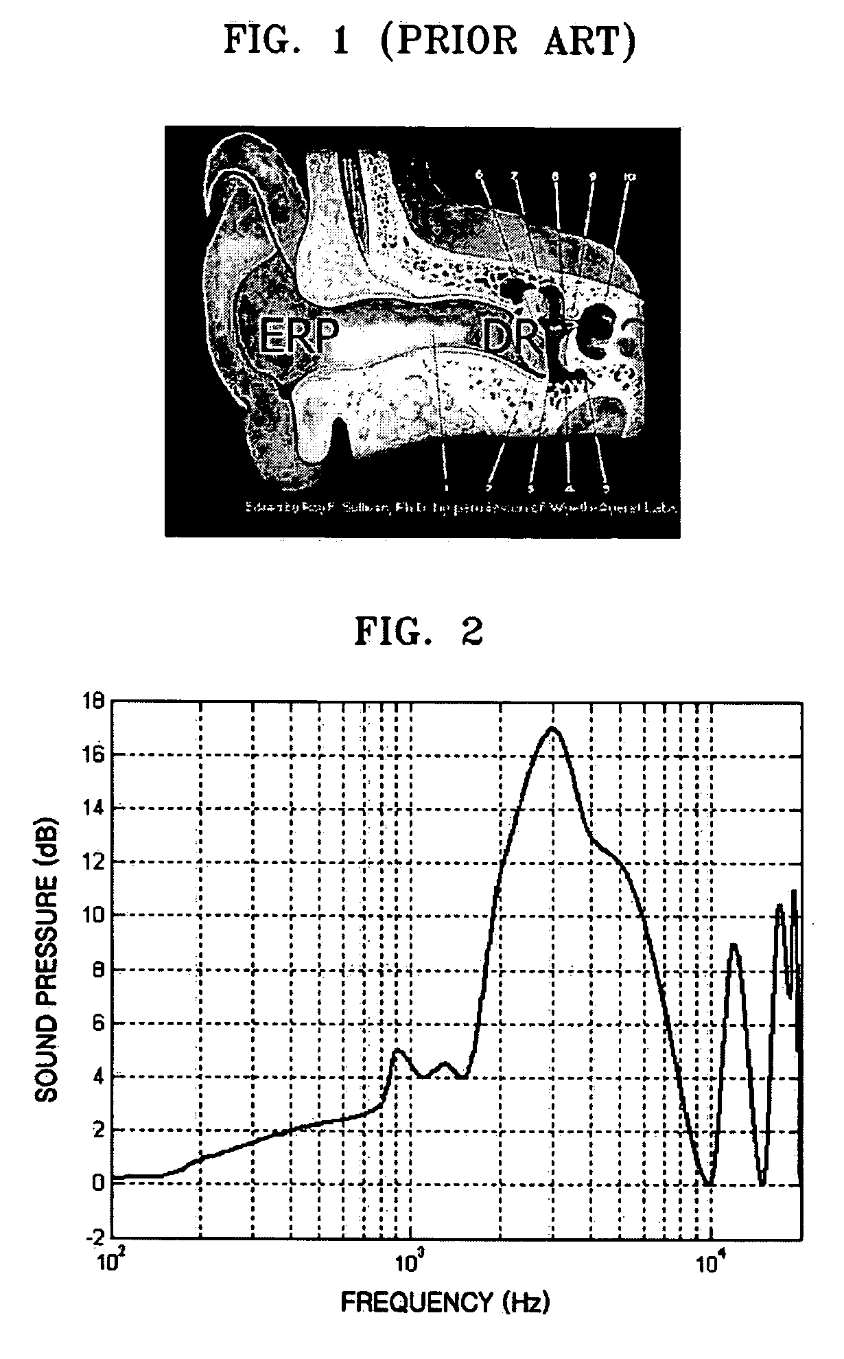
[0030]FIG. 2 is a graph illustrating a resonance waveform between an ear reference point (ERP) and a drum reference point (DRP) of a human ear.

[0031] Referring to FIG. 2, a resonance waveform having a sound pressure that is increased by more than 15 dB at around a 1˜10 KHz band due to a sealed space between the ERP and the DRP is measured. The ERP-DRP resonance waveform can be measured by inserting a probe microphone into an ear of a person or a dummy head.

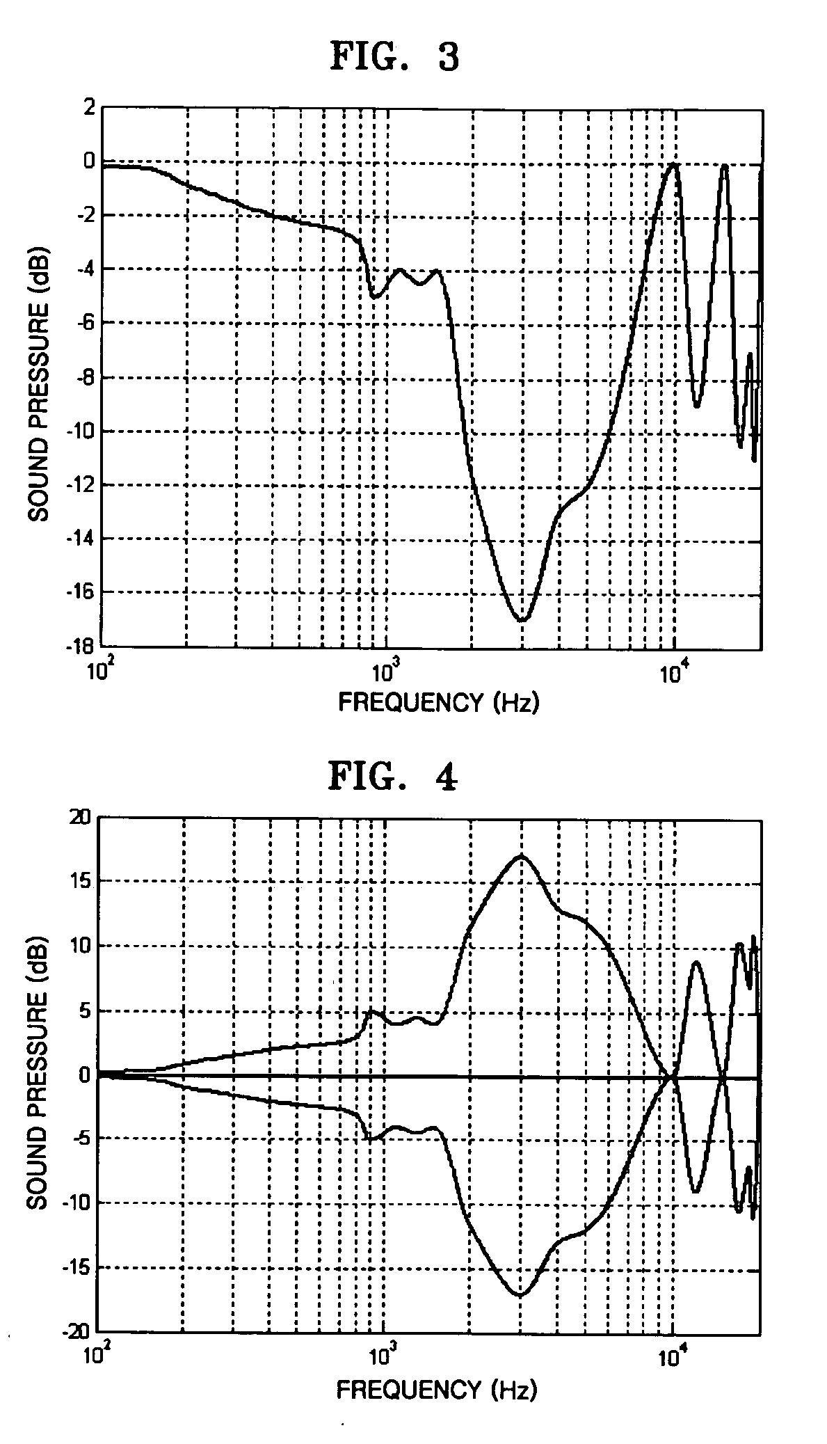
[0032]FIG. 3 is a graph illustrating a compensation waveform obtained by inverting the resonance waveform of FIG. 2.

[0033] Referring to FIG. 3, the compensation wavefo...


PUM


Abstract

An apparatus and method of encoding an audio signal and an apparatus and method of decoding an audio signal. The audio decoding method includes: generating an audio signal by decoding an input signal, and transforming an original waveform of the generated audio signal into a compensation waveform that is compensated for an acoustic resonance effect in the audio signal. Therefore, an audio signal having excellent sound quality without an amplified middle band can be heard via earphones, headphones, or a phone earpiece by using an inverse compensation waveform to compensate an ERP-DRP resonance effect, which is an acoustic resonance effect generated due to the structure of the human ear.

Description

CROSS-REFERENCE TO RELATED APPLICATIONS [0001] This application claims priority from U.S. Provisional Patent Application No. 60 / 576,617, filed on Jun. 4, 2004, and No. 60 / 578,862, filed on Jun. 14, 2004, in the U.S. Patent and Trademark Office, and Korean Patent Application No. 2004-43075, filed on Jun. 11, 2004, in the Korean Intellectual Property Office, the disclosures of which are incorporated herein in their entirety by reference.BACKGROUND OF THE INVENTION [0002] 1. Field of the Invention [0003] The present general inventive concept relates to an apparatus and a method of encoding an audio signal and an apparatus and a method of decoding an audio signal. [0004] 2. Description of the Related Art [0005]FIG. 1 illustrates the structure of a human ear used to detect sound. [0006] Referring to FIG. 1, when an ear reference point (ERP) on an external part of the human ear is sealed by earphones, headphones, a phone ear piece, etc. a sealed space is formed between the ERP and a drum ...

Claims


Application Information

Patent Timeline
Patent Type & Authority Applications(United States)
IPC IPC(8): H04N5/76H03M7/30
CPCG10L21/0264H04R25/505G10L21/0364H03M7/30
Inventor LEE, JOON-HYUNJANG, SEONG-CHEOL
Owner SAMSUNG ELECTRONICS CO LTD
Why Eureka
Try Eureka