Subcutaneous analyte sensor
an analyte sensor and subcutaneous technology, applied in the field of implantable sensors, can solve the problems of large and expensive apparatus, no of these methods has yet acquired practical significance, and signal instability
- Summary
- Abstract
- Description
- Claims
- Application Information
AI Technical Summary
Problems solved by technology
Method used
Image
Examples
first embodiment
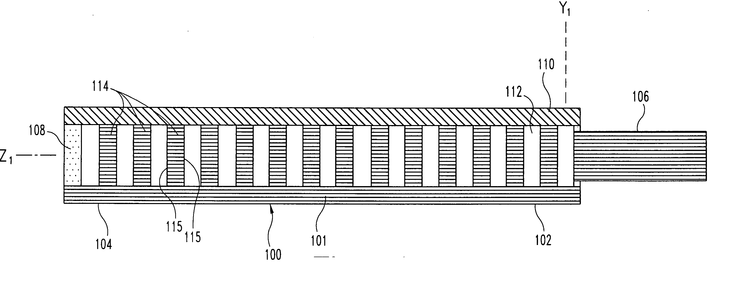
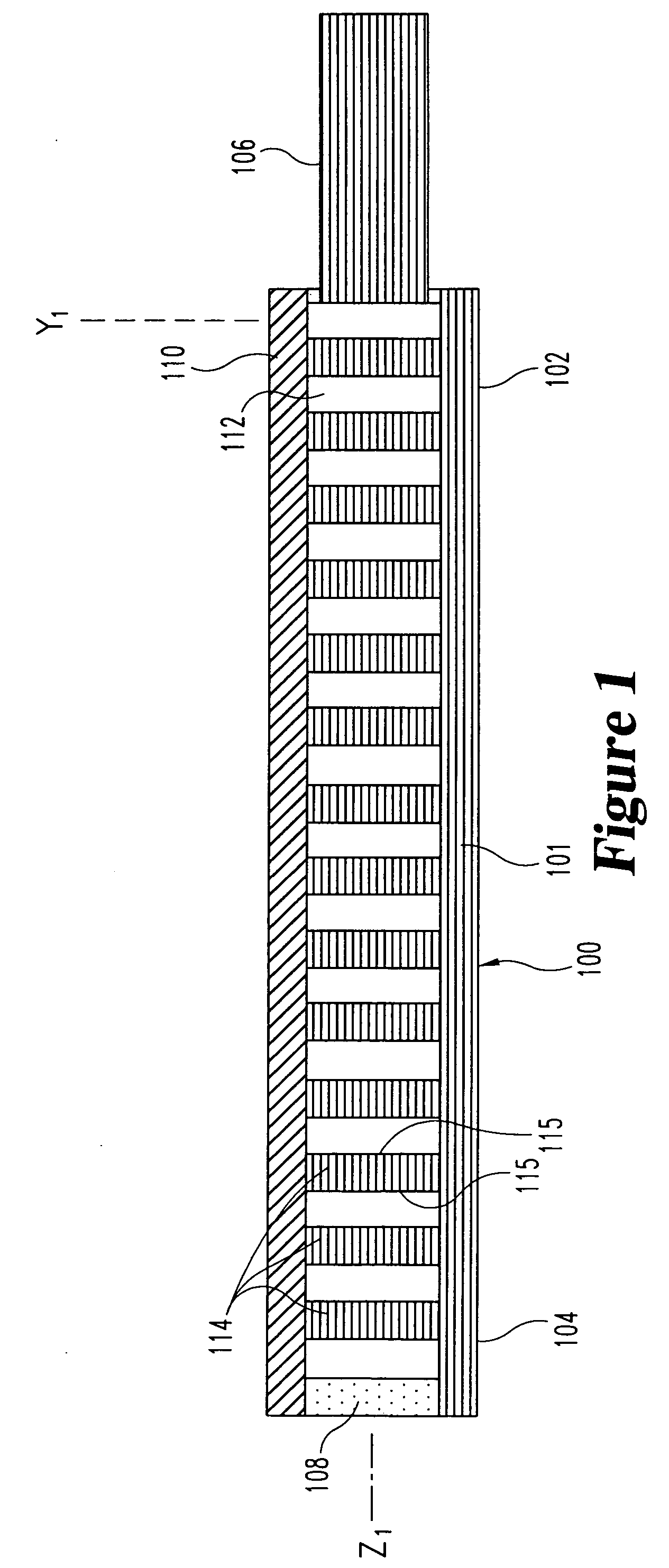
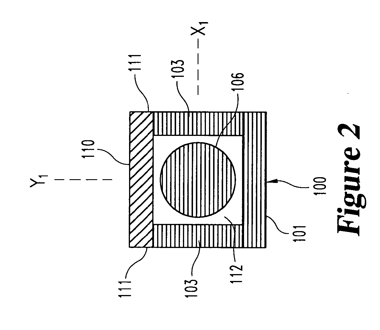
[0061] the optical-sensing element of the invention is illustrated in FIGS. 1-3. The optical-sensing element includes a body 100, a semi-permeable membrane 110 and a refractive element 114. The body 100 and membrane 110 are oriented to define a cavity 112. The refractive element 114 and the analyte or analytes of interest (not shown) are disposed in the cavity 112. The semi-permeable membrane 110 is substantially permeable to the analyte(s), but substantially impermeable to background species in the biological matrix.
[0062] Preferably, the body 100 of the optical-sensing element has a generally “U” or “V”-shaped cross-section, and comprises a molded plastic. The body 100 has a base portion 101 and two opposing side walls 103. Each of the side walls 103 includes an upper edge 111. The body 100 has a proximal end 102 and a distal end 104, and is preferably less than 2 mm in length. A light-transmitting conduit 106, here a single optical fiber, is optically coupled to the proximal end ...
second embodiment
[0067] the invention is illustrated in FIGS. 4-6. The body 200 of the optical-sensing element comprises two parallel, elongated members 203, each having an upper edge 211 and a lower edge 213. The body is preferably formed of molded plastic and is dimensioned in similar manner to the embodiment of FIGS. 1-3. The body 200 also includes a proximal end 202 and a distal end 204. A light-transmitting conduit 206, here a single optical fiber, is sealed in an orifice in the proximal end 202. The distal end 204 preferably comprises a light-absorbing material 208. In this embodiment, a first semi-permeable membrane 210 is attached to the top edges 211 of the elongated members 203, and a second semi-permeable membrane 209 is attached to the bottom edges 213 of the elongated members 203.
[0068] The elongated members 203 and semi-permeable membranes 209 and 210 define a cavity 212. The cavity contains the analyte of interest (not shown) and a refractive element 214. The refractive element compri...
third embodiment
[0069] the invention is illustrated in FIGS. 7-9. In this embodiment, the body 300, base portion 301, side walls 303, light-transmitting conduit 306, light-absorbing material 308, membrane 310, edges 311, cavity 312, and respective proximal and distal ends 302 and 304 are as described in the embodiment of FIGS. 1-3. The refractive element 314 comprises a plurality of beads, which provide a plurality of reflective or refractive surfaces 315. The composition of the beads is normally not important, as long as they provide suitable reflective or refractive surfaces. Glass beads, or beads formed from polymers such as polystyrene, are particularly suitable. The composition, diameter, and number of the beads can be varied to achieve a packing arrangement which provides optimal amplification of light by multiple reflections off the bead surfaces 315. A similar effect is achieved when refractive powders are provided in the cavity in place of the beads.
PUM
| Property | Measurement | Unit |
|---|---|---|
| refractive index | aaaaa | aaaaa |
| refractive index | aaaaa | aaaaa |
| refractive index | aaaaa | aaaaa |
Abstract
Description
Claims
Application Information
 - R&D
- Intellectual Property
- Life Sciences
- Materials
- Tech Scout
- Unparalleled Data Quality
- Higher Quality Content
- 60% Fewer Hallucinations
Browse by: Latest US Patents, China's latest patents, Technical Efficacy Thesaurus, Application Domain, Technology Topic, Popular Technical Reports.
© 2025 PatSnap. All rights reserved.Legal|Privacy policy|Modern Slavery Act Transparency Statement|Sitemap|About US| Contact US: help@patsnap.com


