Candle assembly including a fuel element and a wick holder

a fuel element and wick holder technology, applied in the field of casing assemblies, can solve the problems of flame extinguishing, leaving and a pool of unconsumed fuel in the bottom

Inactive Publication Date: 2005-12-08
SC JOHNSON & SON INC
View PDF99 Cites 18 Cited by
  • Summary
  • Abstract
  • Description
  • Claims
  • Application Information

AI Technical Summary

Problems solved by technology

When the level of wax in the candle assembly drops below the top wall of the pedestal, a flame on the wick is extinguished because of a lack of fuel, thereby leaving a pool of unconsumed fuel in the bottom of the can.
When the top surface of the melted wax falls below the level of the dish shaped recess, a flame on the wick is aut

Method used


Image

  • Candle assembly including a fuel element and a wick holder
  • Candle assembly including a fuel element and a wick holder
  • Candle assembly including a fuel element and a wick holder

Examples


Embodiment Construction

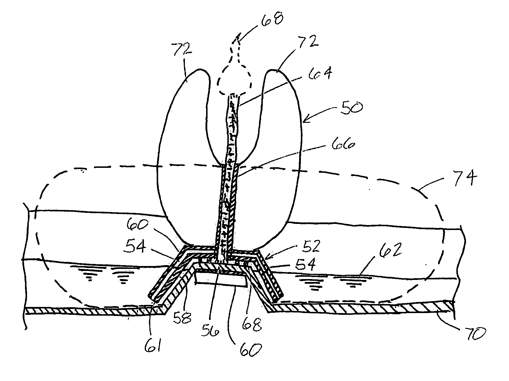
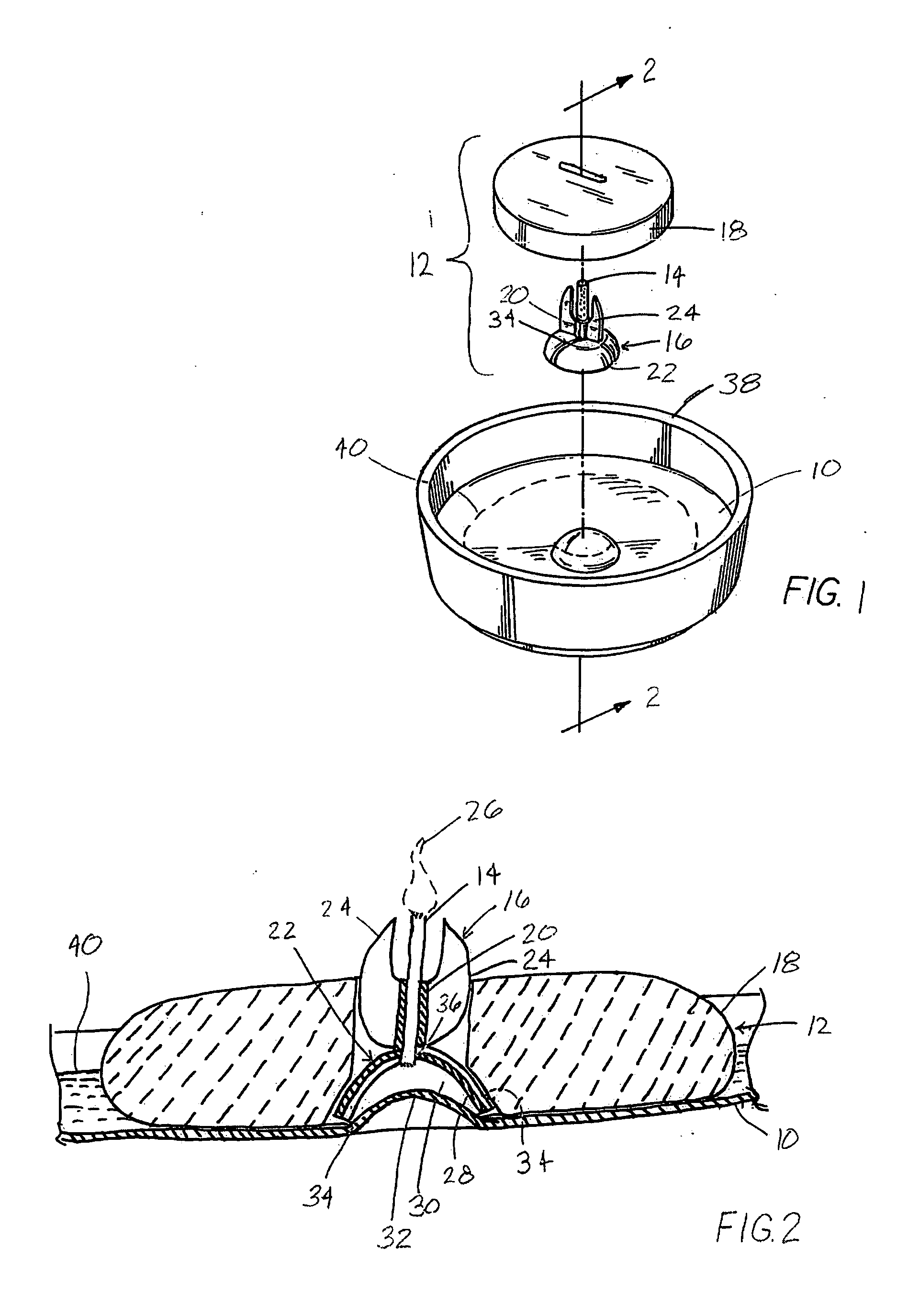
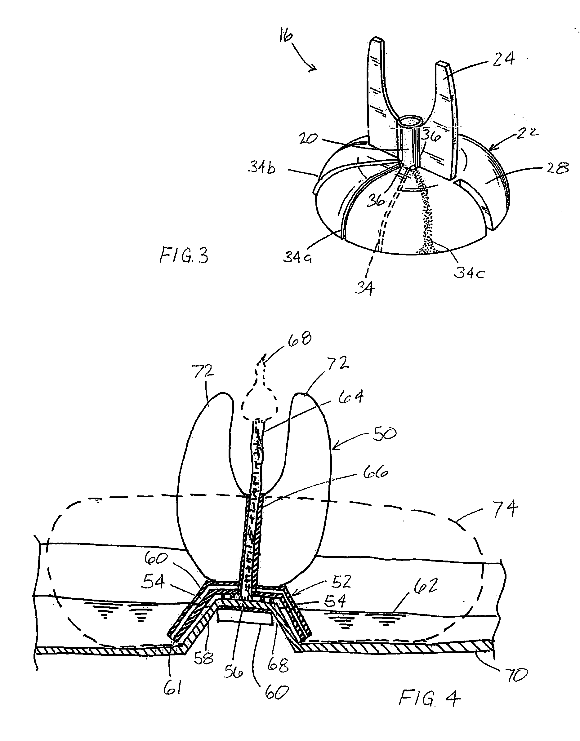
[0025] In one embodiment of the present invention, a melting plate candle assembly includes a melting plate carried by a support base and a fuel element disposed on the melting plate. The fuel element includes a fuel charge surrounding a wick carried by a wick holder. A capillary lobe disposed at a low point on the melting plate engages and / or positions the wick, wick holder, and fuel charge in such a manner as to provide an advantageous positioning thereof for quickly melting the fuel charge, as well as to create a capillary flow of liquefied or melted fuel from a pool formed on the melting plate to the wick positioned above the melting plate in the wick holder, which in one operative embodiment is placed in such close relationship to the capillary lobe as to create a very narrow gap, or capillary space, between the lobe and the wick holder. The capillary space, which may be for example from approximately 0.01 to about 0.04 inches (0.2-1.0 mm), or about 0.02 inches (0.5 mm), allows...


PUM


Abstract

A melting plate candle assembly includes a wick holder that retains a wick spaced above a melting plate and a base portion having one or more capillary paths disposed therein that are adapted to draw liquid, such as melted candle wax, from a pool retained on the melting plate to the wick by capillary action therein.

Description

CROSS REFERENCE TO RELATED APPLICATIONS [0001] This application is a continuation-in-part of U.S. patent application Ser. No. 10 / 780,028, filed Feb. 17, 2004, which is incorporated herein by reference in the entirety thereof.REFERENCE REGARDING FEDERALLY SPONSORED RESEARCH OR DEVELOPMENT [0002] Not applicable SEQUENTIAL LISTING [0003] Not applicable BACKGROUND OF THE INVENTION [0004] 1. Field of the Invention [0005] The present invention relates generally to candle assemblies, and more particularly to candle assemblies including a capillary path disposed between a wick and a support for a fuel charge. [0006] 2. Description of the Background of the Invention [0007] In many common candle assemblies, melted fuel from a fuel charge surrounding a wick is drawn upwardly through the wick to a burning flame thereon by capillary action. One such candle assembly is a basic taper or pillar candle having a charge of substantially solidified candle wax disposed around and supporting a fibrous wi...

Claims


Application Information

Patent Timeline
IPC IPC(8): F23D3/16F21V37/00
CPCF21V37/00F23D3/16
Inventor FURNER, PAUL E.
Owner SC JOHNSON & SON INC
Why Eureka
Try Eureka