Sir measurement device and sir measurement method

a measurement device and measurement method technology, applied in the direction of transmission, electrical equipment, transmission monitoring, etc., can solve the problems of insufficient measurement of sir value at a high degree of accuracy, the degree of freedom of sir measurement and the configuration of the apparatus tends to decrease, and the above described conventional sir measurement method and the static error of the theoretical value cannot be correctly corrected. , to achieve the effect of high degree of freedom and high degree of accuracy

Inactive Publication Date: 2005-12-08
PANASONIC CORP
View PDF5 Cites 11 Cited by
  • Summary
  • Abstract
  • Description
  • Claims
  • Application Information

AI Technical Summary

Benefits of technology

[0015] It is an object of the present invention to provide an SIR measuring apparatus and method capable of me...

Problems solved by technology

However, in a system carrying out RAKE combining like a CDMA communication, when an SIR value after RAKE combining is calculated from RSCP and ISCP values obtained for each finger and the SIR value is corrected, the above described conventional SIR measuring method and apparatus canno...

Method used


Image

  • Sir measurement device and sir measurement method
  • Sir measurement device and sir measurement method
  • Sir measurement device and sir measurement method

Examples


embodiment 1

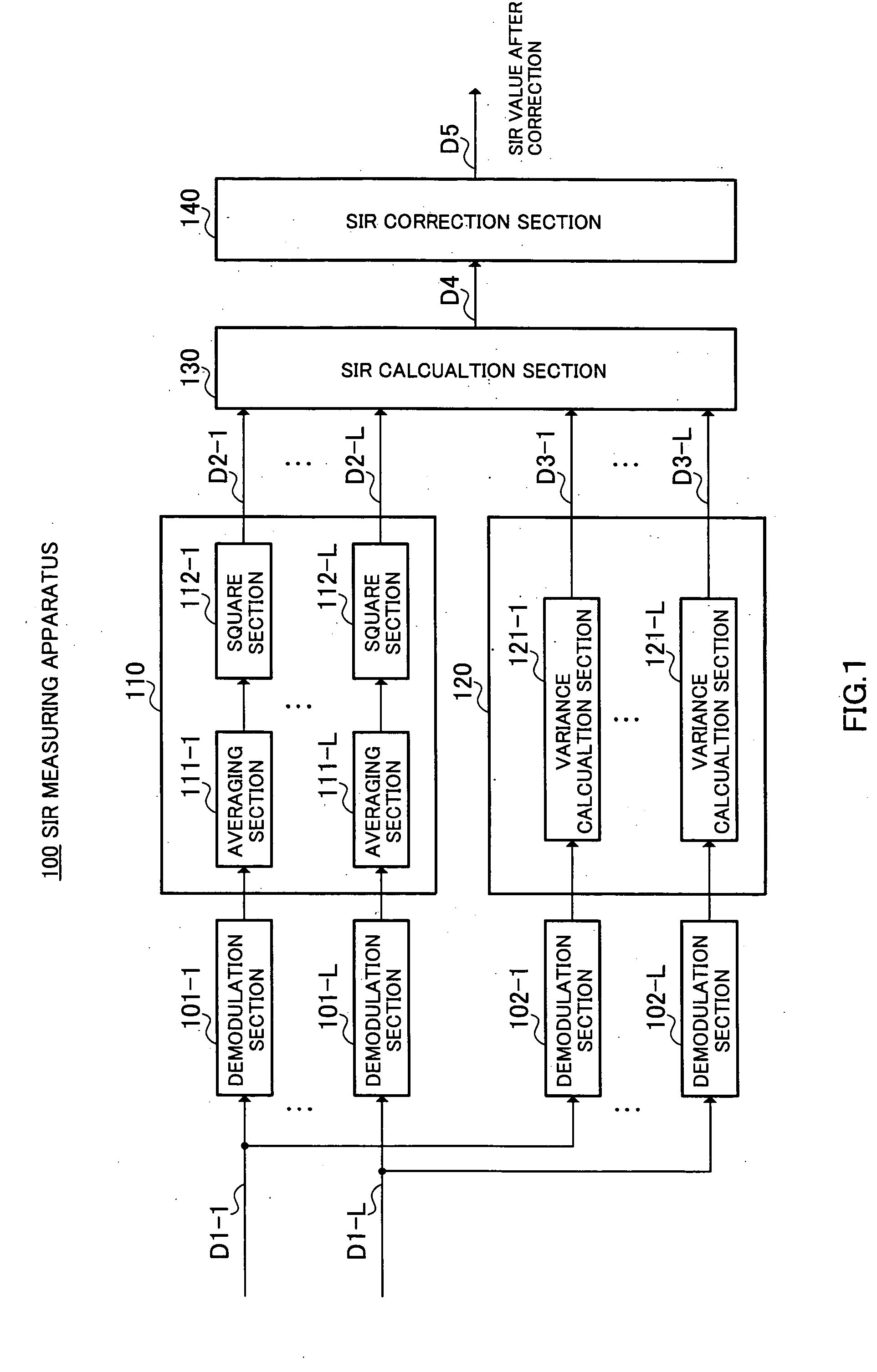
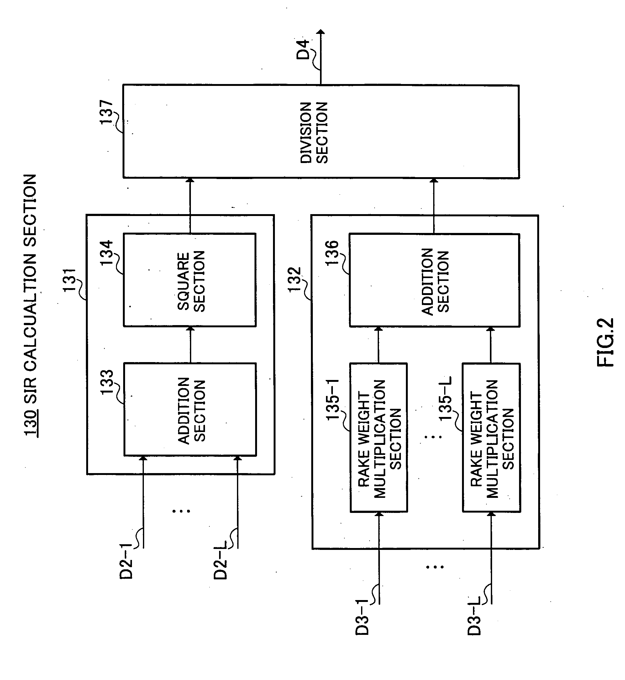
[0025] In FIG. 1, reference numeral 100 denotes an SIR measuring apparatus according to an Embodiment of the present invention as a whole, which is roughly divided into an RSCP calculation section 110 that calculates RSCP (desired signal power) of each finger (the number of fingers is assumed to be L in this embodiment), an ISCP calculation section 120 that calculates an ISCP (interference signal power) of each finger, an SIR calculation section 130 that calculates an SIR after RAKE combining from the desired signal power value D2 and interference signal power value D3 calculated by the RSCP calculation section 110 and ISCP calculation section 120, and an SIR correction section 140 that corrects the SIR calculated by the SIR calculation section 130.

[0026] The SIR measuring apparatus 100 inputs despread signals D1-1 to D1-L of respective fingers of a received signal to demodulation sections 101-1 to 101-L, 102-1 to 102-L. The respective demodulation sections 101-1 to 101-L, 102-1 to...

embodiment 2

[0049]FIG. 7 shows the configuration of an SIR correction section 200 according to Embodiment 2 of the present invention. That is, this embodiment uses the SIR correction section 200 in FIG. 7 instead of the SIR correction section 140 in FIG. 3 explained in Embodiment 1. This embodiment differs from Embodiment 1 only in the SIR correction section 200, and therefore only the SIR correction section 200 will be explained.

[0050] The SIR correction section 200 includes an approximate coefficient calculation section 203 and a multiplication section 204. The approximate coefficient calculation section 203 receives received powers D6-1 to D6-L of their respective fingers and the approximate coefficient calculation section 203 calculates approximate coefficient a corresponding to the ratio of the received power of each finger. This approximate coefficient a is sent to the multiplication section 204. The multiplication section 204 carries out a multiplication using the number of fingers L us...


PUM


Abstract

An SIR calculation section 130 calculates an SIR value D4 after RAKE combining from a desired signal power value for each finger calculated by an RSCP calculation section 110 and an interference signal power value for each finger calculated by an ISCP calculation section 120. An SIR correction section 140 corrects the SIR value D4 using the number of discrete signals used to calculate RSCP, the number of discrete signals used to calculate ISCP and the number of fingers L used for RAKE combining. As a result, even when the number of discrete signals used to calculate RSCP is different from the number of discrete signals used to calculate ISCP, it is possible to realize an SIR measuring apparatus 100 capable of resolving a static error with respect to a theoretical value and realizing measurements at a high degree of accuracy and freedom.

Description

TECHNICAL FIELD [0001] The present invention relates to an apparatus and method for measuring an SIR after RAKE combining based on a communication scheme which performs RAKE combining such as a CDMA communication system in particular. BACKGROUND ART [0002] Conventionally, an SIR (Signal to Interference Ratio) is widely used as an index for performing various types of control such as transmit power in the field of radio communications. For example, a communication system using a CDMA (Code Division Multiple Access) scheme measures an SIR after RAKE combining and controls transmit power based on this measurement result. By so doing, it is possible to control transmit power at each user to a minimum necessary level, suppress interference to other users from each user and obtain desired reception quality (that is, SIR). [0003] According to closed-loop transmit power control of this transmit power control, a receiving side apparatus presets a target SIR as target reception quality and se...

Claims


Application Information

Patent Timeline
IPC IPC(8): H04B1/707H04B17/00
CPCH04B1/7115H04B17/336
Inventor MURASE, TAICHI
Owner PANASONIC CORP
Why Eureka
Try Eureka