Fracture walker with horseshoe heel pad beneath insole

a technology of foot platform and foot pad, which is applied in the field of fracture walker, can solve the problems of unrestrained calcaneus to relocate within the fracture walker, shift or twist of the foot platform, and patient loss of balance,

Inactive Publication Date: 2005-12-15
EUROPEAN BIOINFORMATICS INSTITUTE
View PDF29 Cites 46 Cited by
  • Summary
  • Abstract
  • Description
  • Claims
  • Application Information

AI Technical Summary

Problems solved by technology

A misalignment of step or nonlevel walking surface may result in a shifting or twisting of the foot platform as weight is applied through the lower limb (loading response phase of the walking cycle).
This shifting or twisting can cause a loss of balance to the patient to the extent that additional weight is shifted to the lower limb as the upper body is rotated to regain balance.
This twisting of the foot platform relative the upper body

Method used


Image

  • Fracture walker with horseshoe heel pad beneath insole
  • Fracture walker with horseshoe heel pad beneath insole
  • Fracture walker with horseshoe heel pad beneath insole

Examples


Embodiment Construction

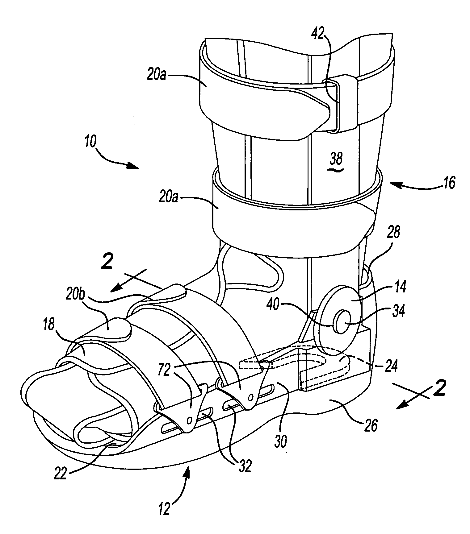
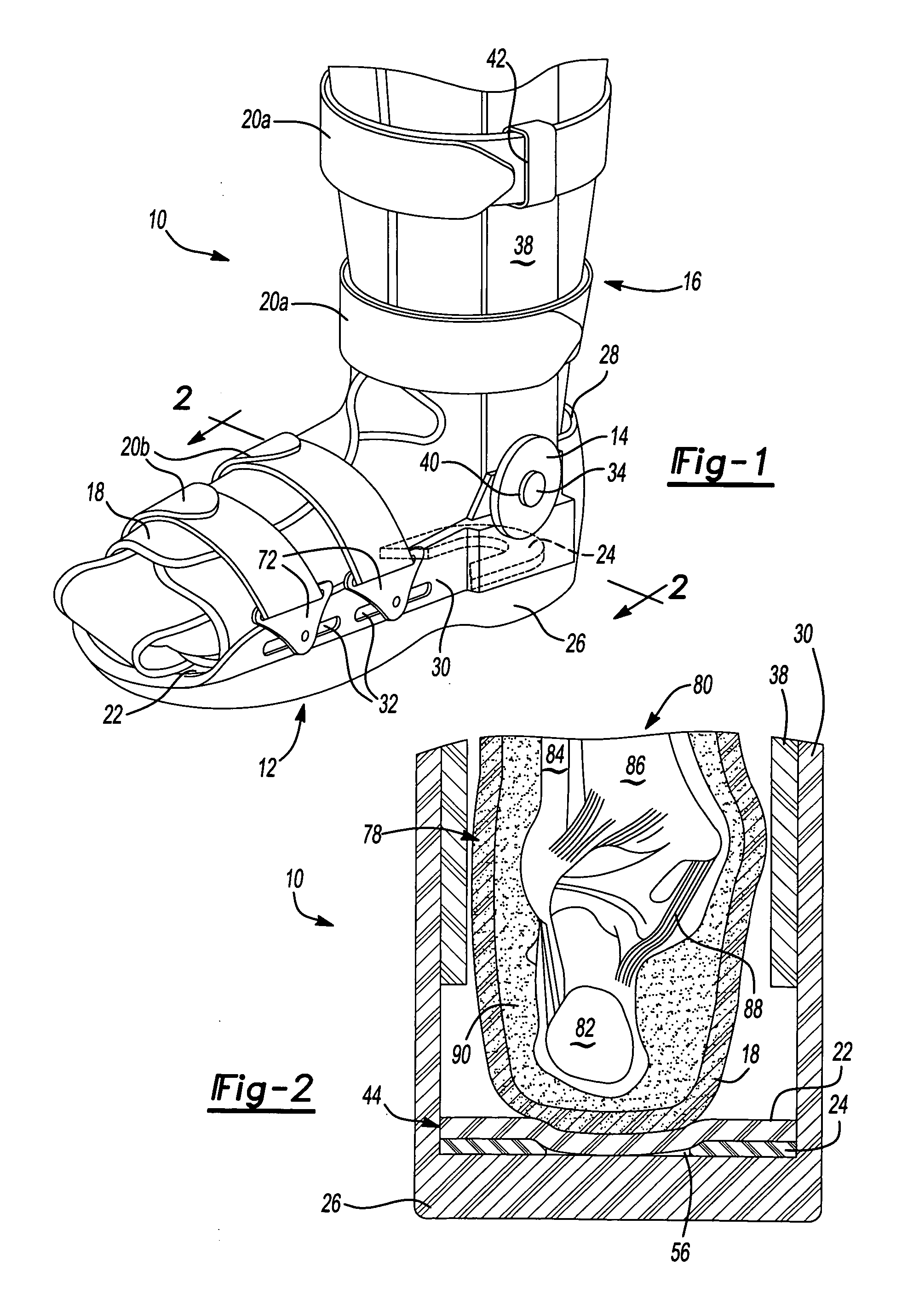
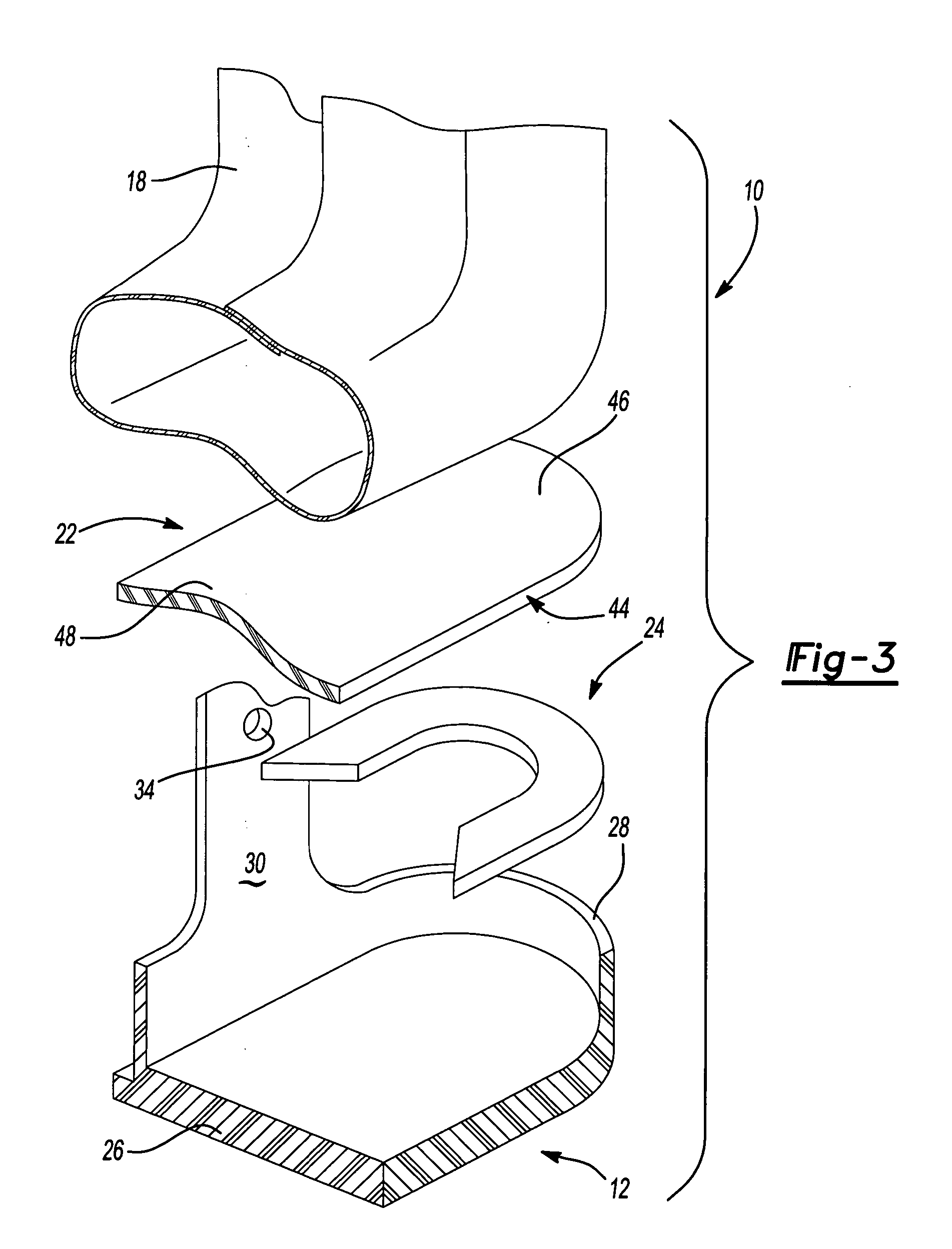
[0015] The following description of the preferred embodiment of a method and apparatus for locating a calcaneus within a fracture walker is merely exemplary in nature and is in no way intended to limit the invention, its applications or uses. It should be appreciated that the locating device, while shown as a horseshoe shaped member, may be any shape that allows the calcaneus to be properly positioned within a fracture walker.

[0016]FIG. 1 illustrates a fracture walker in accordance with the present invention referred to generally as numeral 10. Fracture walker 10 includes a foot platform 12, a pair of hinge assemblies 14, a leg assembly 16, a liner 18, straps 20, an insole 22, and a locating device 24. Foot platform 12 includes a base 26 with a rear lip 28 around the back of a foot and frame members 30 extending therefrom around the medial and lateral sides of a foot. Frame members 30 have strap attachment apertures 32 and hinge attachment locations 34 formed therein. Leg assembly ...


PUM


Abstract

A method and apparatus for locating a calcaneus within a fracture walker is disclosed. The apparatus includes a locating device that has a notch formed therein, and an insole covering the locating device whereby the ankle forms a depression in the insole adjacent the notch when force is applied through the ankle on the insole.

Description

FIELD OF THE INVENTION [0001] The present invention generally relates to a fracture walker, and more particularly to a method and apparatus for locating the foot within a fracture walker. BACKGROUND OF THE INVENTION [0002] Fracture walkers are often used to stabilize the ankle and lower extremity to encourage healing after a surgery or injury. A typical fracture walker can be used to limit the ankle flexion to either a fixed position or to a chosen range of dorsiflexion and / or plantarflexion. A typical fracture walker includes a foot platform portion and a lower leg portion. Generally, adjustable hinges are located between these two portions in order to allow some degree of ankle movement or to lock the ankle from movement. A typical fracture walker is sized such that it can be used for either the right or left leg thereby requiring the foot portion to accommodate either a right or left foot. Accordingly, the foot portion is generally rectangular to accommodate the various shapes of...

Claims


Application Information

Patent Timeline
IPC IPC(8): A61F5/01A43B1/00
CPCA61F5/0127
Inventor SCHWARTZ, RICHARD B.
Owner EUROPEAN BIOINFORMATICS INSTITUTE
Why Eureka
Try Eureka