Rainproof recessed outlet box

Active Publication Date: 2005-12-15
ARLINGTON INDS
View PDF10 Cites 14 Cited by
  • Summary
  • Abstract
  • Description
  • Claims
  • Application Information

AI Technical Summary

Benefits of technology

[0007] A first advantage of the recessed electrical box is that it properly recesses or positions the box at the proper depth with respect to the outer surface of the building. The electrical box may include one or more outward extending flanges that provide a positioning mechanism to recess the electrical box at the correct depth within the building's surface. The positioning mechanism is functional for both a retrofit situation, in which the finished layer such as siding or stucco is installed, or in a building under construction in which the finished layer has not been installed.
[0008] A second advantage is that a while-in-use cover member, which renders the recessed electrical box rainproof, is minimal in size with respect to the box. Cover members are typically molded of expensive impact resistant plastic to meet electrical code. Keeping the cover minimal in size with respect to the box lowers the cost of production of the outlet box.
[0009] A further advantage is that the recessed electrical box positions an enclosed electrical device substantially behind the outer surface of the building. This p

Problems solved by technology

Cover members are typically molded of expensive

Method used


Image

  • Rainproof recessed outlet box
  • Rainproof recessed outlet box
  • Rainproof recessed outlet box

Examples


first embodiment

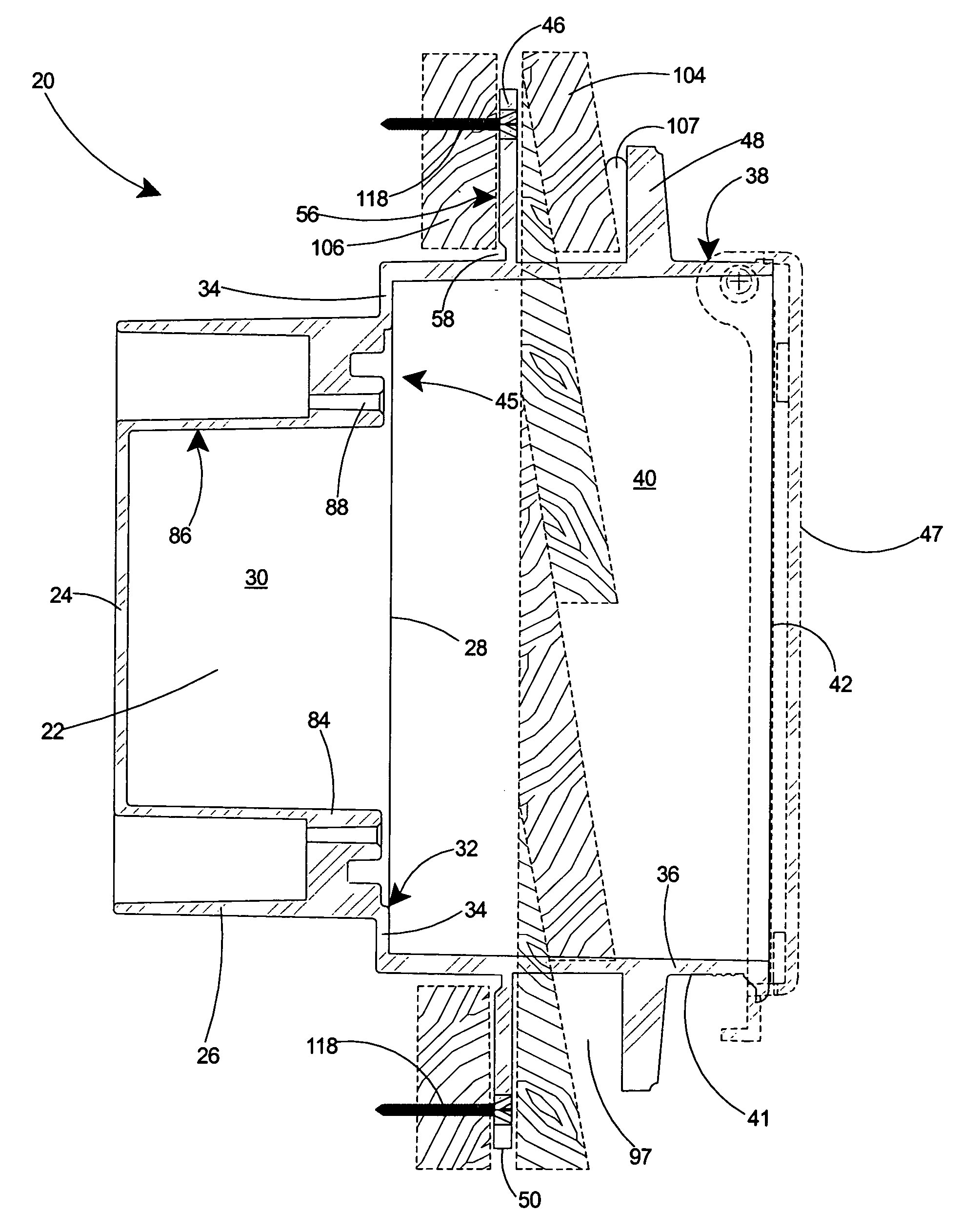
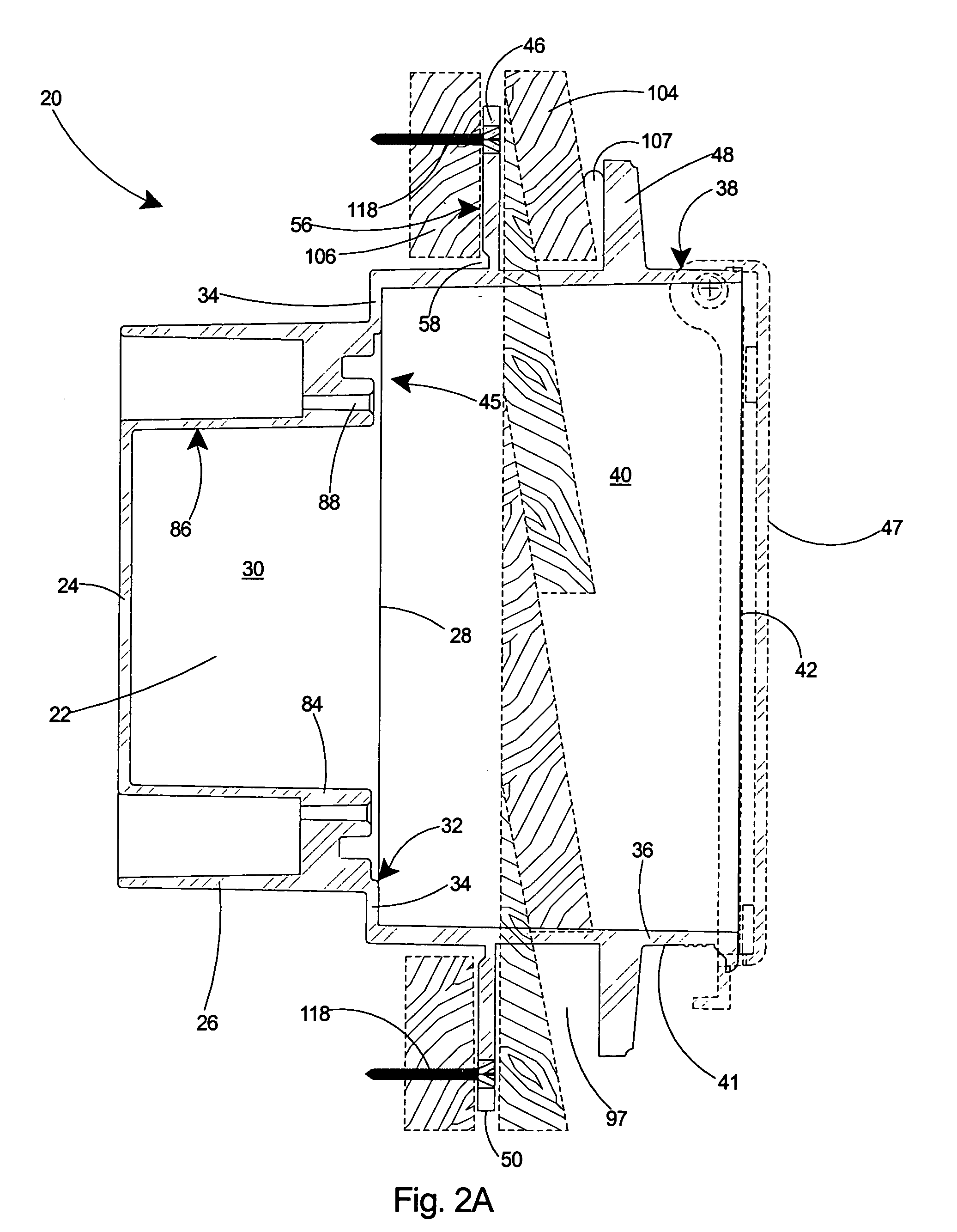
[0054] Referring to FIG. 17, the three embodiments of the recessed electrical box 20, 100, and 110 are shown installed on the outside surface 138 of a building. The flanges 46, 48 serve as a positioning arrangement 139 for positioning the electrical box 20, 100, 110 at the correct depth with respect to the wall. For the recessed electrical box 20, shown at the top of the figure, either the inner 46 or outer 48 flange serves as the positioning arrangement, depending on the application. If the siding 104 has not been installed, the installer simply makes a hole in the substrate 106 and pushes the box 20 into the hole until the rear surface of the inner flange 46 contacts the outer surface 140 of the substrate 106. Fasteners 118 are then driven through the inner flange 46 to secure the recessed electrical box 20 to the substrate 106. Siding 104 is then inserted into the gap 97 surrounding all four sides of the electrical box 20 and the siding 104 is then fastened to the substrate 106.

[...

third embodiment

[0056] the recessed electrical box 110, shown at the bottom of FIG. 17, includes only a breakaway inner flange 46. If the building is under construction and the substrate 106 exposed, the inner flange 46 serves as a positioning arrangement for mounting the electrical box 110 at the proper depth. Fasteners 118 can then be driven through the inner flange 46 of the recessed electrical box 110 to secure it to the substrate 106.

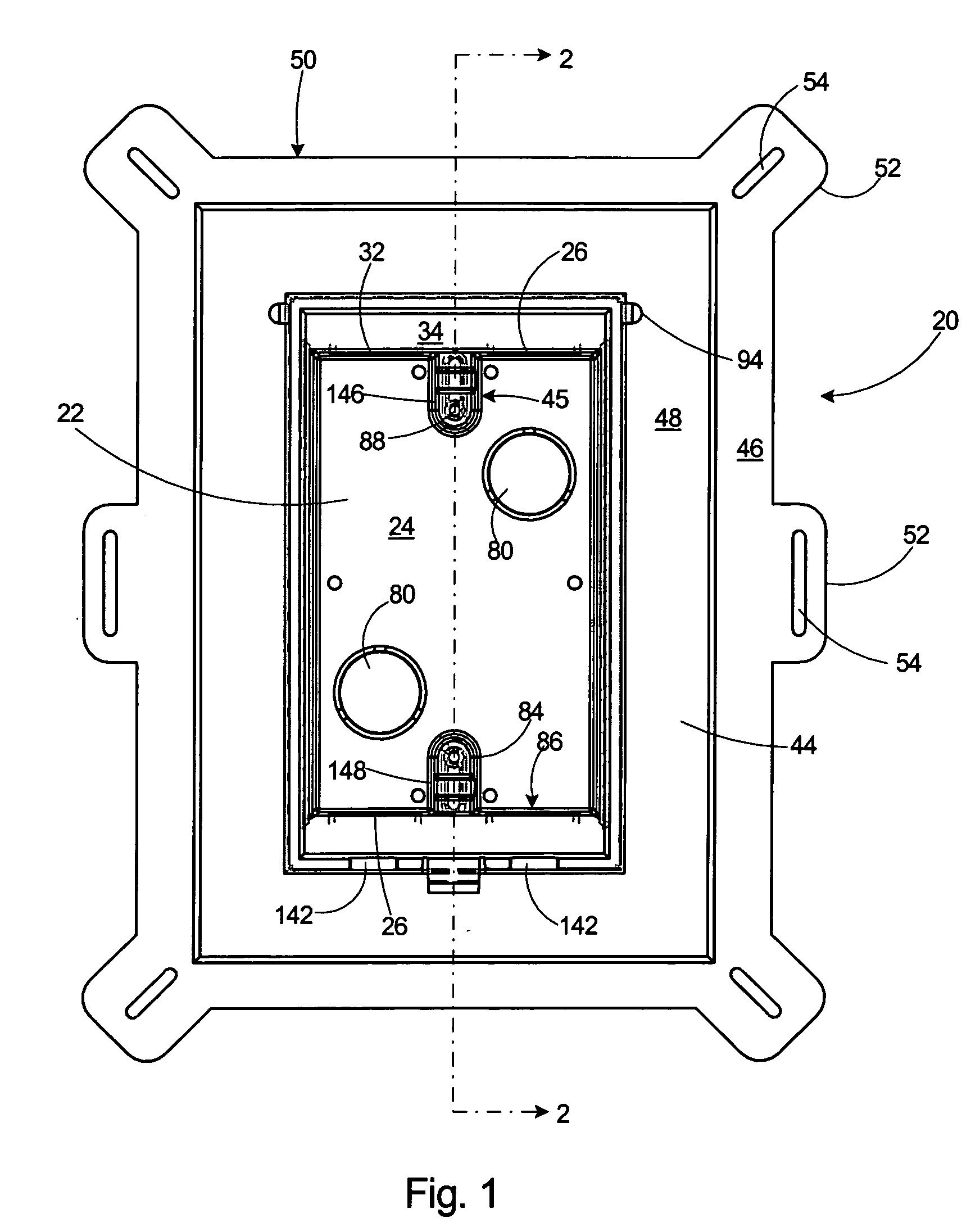
[0057] Regardless of which embodiment of the recessed electrical box 20, 100, 110 is used, the electrical device will be positioned substantially behind the outside surface 138 of the building, thereby providing a great deal of protection to the electrical device. As shown in FIG. 4, the planar front edge 42 of the recessed electrical box 20 further includes one or more U-shaped slots 142 in the side walls 36 of the second box 38. As shown in FIG. 13, the cover member 47 also includes one or more U-shaped slots 144 in the stiffening side wall 95. When the cover me...


PUM


Abstract

A recessed electrical box with a closeable cover member and at least one outward extending flange. The flange serves as a positioning arrangement to recess the electrical box at the correct depth with respect to the surface in which it will be mounted. The recessed electrical box is includes of two pieces, including a one-piece electrical box and a one-piece cover member. The cover member is of minimal size with respect to the electrical box to minimize the cost of construction. The electrical box can be installed on an exterior wall, including either a finished or an unfinished wall. The outward extending flange may include an inner flange for positioning the recessed electrical box with respect to the outer surface of the substrate on an unfinished building. The inner flange is removable to facilitate installation on a finished building, in which the finish layer such as siding or stucco is installed. The recessed electrical box may include a second, outer flange, for recessing the box at the correct depth with respect to a finished surface and to occlude from view the sidewalls of the box at their juncture with the finished surface.

Description

[0001] This application is a Continuation-In-Part of U.S. patent application Ser. No. 10 / 863,942 filed Jun. 9, 2004 and still pending.FIELD OF THE INVENTION [0002] This invention relates to electrical junction boxes and specifically to a recessed outlet box that secures an electrical device substantially behind the exterior of a building for accommodating and protecting a duplex outlet or other electrical device therein. BACKGROUND OF THE INVENTION [0003] In the mounting of outlets to the exterior of a building, covered electrical boxes are commonly used for providing a rainproof electrical enclosure. These outdoor electrical enclosures are typically multi-piece structures, typically comprising three or more separate pieces to provide a weatherproof enclosure. [0004] U.S. Pat. No. 5,280,135 (hereinafter the '135 patent), for example, discloses an outdoor weatherproof electrical outlet cover adapted to be attached in weatherproof connection to an electrical outlet. The outlet cover i...

Claims


Application Information

Patent Timeline
IPC IPC(8): H02G3/08H02G3/12H01H9/02H02G3/14
CPCH02G3/123H02G3/14Y10S248/906
Inventor GRETZ, THOMAS J.
Owner ARLINGTON INDS
Why Eureka
Try Eureka