Reaming and stabilization tool and method for its use in a borehole

a stabilization tool and drilling tool technology, applied in the field of earth formation drilling, can solve the problems of reducing the life span and functionality of the underreamer, affecting the drilling fluid flow through the underreamer, and affecting the drilling effect, so as to achieve the effect of substantially reducing the disadvantages and eliminating the problems of the underreamer life span

Active Publication Date: 2005-12-15
HALLIBURTON ENERGY SERVICES INC
View PDF99 Cites 41 Cited by
  • Summary
  • Abstract
  • Description
  • Claims
  • Application Information

AI Technical Summary

Benefits of technology

[0004] In accordance with the present invention, the disadvantages and problems associated with underreamer life span and functionality have been substantially reduced or eliminated. In particular, the problem of clogging of the underreamer, which may prevent proper retraction of the cutting arms and thereby cause premature breakage of the cutting arms, has been reduced or eliminated.
[0006] Technical advantages of certain embodiments of the present invention include expandable underreaming or cutting arms which have significant thickness, yet are still capable of substantially retracting within the underreamer body when not in use. A thicker, more massive cutting arm will be better able to withstand the forces exerted by the formation being cut. Increasing the thickness of the cutting arms may hamper the flow of drilling fluids through the underreamer. Therefore, the underreamer has been designed with thick cutting arms that do not significantly impinge the flow of the drilling fluid.
[0007] Another technical advantage of certain embodiments of the present invention is a clogging resistant design. The cutting arms at full extension will project beyond the body of the underreamer. However, the space formed under the cutting arms may remain closed off from the drilling mud and debris circulating around the exterior of the underreamer. This is the case because the apex of the angle formed under the cutting arms does not extend beyond the periphery of the tubular body. For example, it lies outside of a recess defined by the tubular body for the cutting arms. The cutting arms are also sized to correspond to the opening through which they extend. This design prevents debris from clogging the space behind the cutting arms reducing the possibility that the cutting arms are prevented from retracting into the underreamer. Further, jets of drilling fluid from the interior of the underreamer may be directed into the space under the cutting arms to maintain a flow of drilling fluid away from areas which may otherwise become clogged.

Problems solved by technology

Increasing the thickness of the cutting arms may hamper the flow of drilling fluids through the underreamer.
However, the space formed under the cutting arms may remain closed off from the drilling mud and debris circulating around the exterior of the underreamer.

Method used


Image

  • Reaming and stabilization tool and method for its use in a borehole
  • Reaming and stabilization tool and method for its use in a borehole
  • Reaming and stabilization tool and method for its use in a borehole

Examples


Embodiment Construction

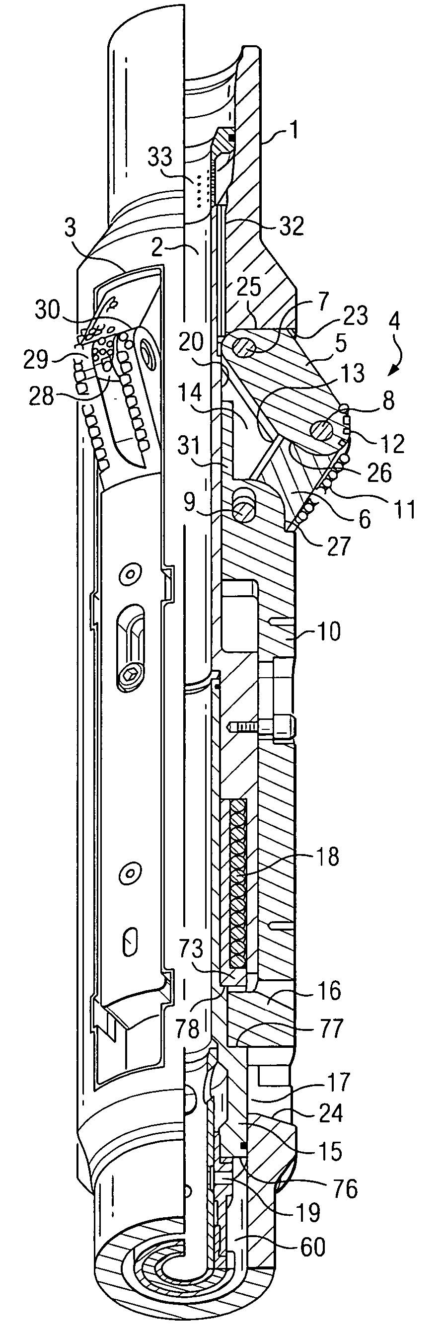
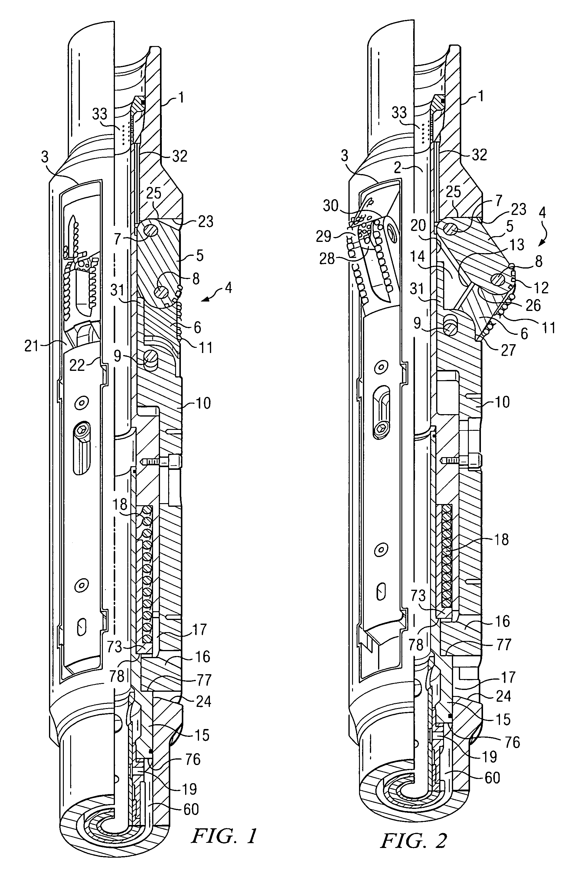
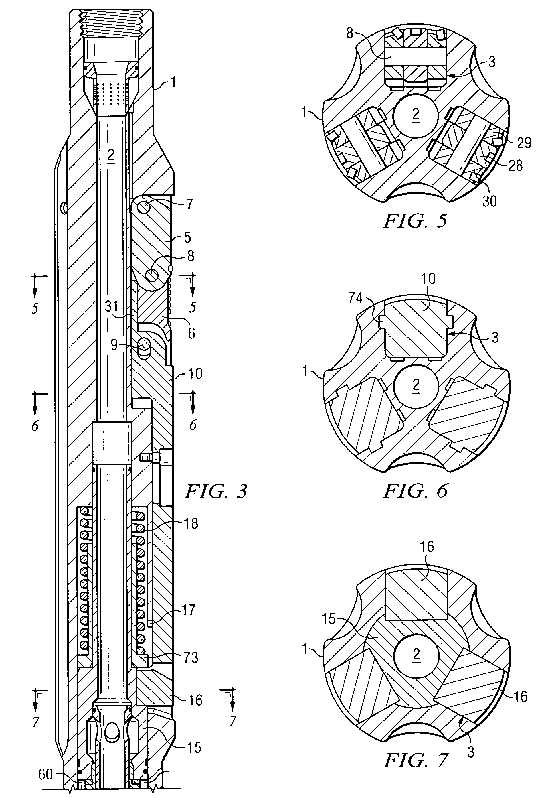
[0026] The present invention relates to a reaming and stabilization tool to be used in a borehole. One embodiment of the present invention may include a tubular body to be mounted between a first section of a drill string and a second section of the drill string. The tubular body may have an axial cavity and, peripherally, housings provided with openings to the outside. A cutter element may be housed in each housing. The cutter element may include at least two cutting arms articulated on each other and on the tubular body. The cutting arms are able to be moved between a retracted position in which they are situated inside their housing and an extension position in which they are deployed outside.

[0027] The tool may also include a drive mechanism arranged inside the tubular body so as to be axially offset with respect to the cutter elements. The drive mechanism is capable of effecting a movement between two extreme positions. The tool may also include a transmission mechanism capabl...


PUM


Abstract

In accordance with an embodiment of the present invention, a drilling tool includes a tubular body defining a longitudinal axial cavity extending therethrough and defining at least one cutter element recess. The drilling tool also includes a cutter element at least partially disposed within the at least one cutter element recess and includes at least first and second cutting arms at least substantially disposed within the cutter element recess in a retracted position. The first and second cutting arms are operable to move from the retracted position to an extended position in which the first and second cutting arms extend at least partially beyond a periphery of the tubular body. The first and second cutting arms and the tubular body enclose a space when the first and second cutting arms are in the extended position.

Description

CROSS-REFERENCE TO RELATED APPLICATIONS [0001] This application is a Continuation-in-Part of International Patent Application Serial No. PCT / BE2004 / 000083 entitled “Reaming and Stabilization Tool For Use in a Borehole” filed on Jun. 9, 2004.TECHNICAL FIELD OF THE INVENTION [0002] This invention relates in general to earth formation drilling, and more particularly to a reaming and stabilization tool and method for its use in a borehole. BACKGROUND OF THE INVENTION [0003] Earth formation drilling is often accomplished using a long string of drilling pipes and tools coupled together. The drilling string is rotated together in order to rotate a cutting bit at the end of the string. This cutting bit creates the hole which the rest of the drilling string moves through. For various reasons, it may be desirable to widen the walls of the hole after it has been created by the cutting bit. Bore-hole underreamers exist to accomplish the widening of the hole. An underreamer may be coupled to the...

Claims


Application Information

Patent Timeline
Patent Type & Authority Applications(United States)
IPC IPC(8): E21B7/28E21B10/32
CPCE21B10/32
Inventor FANUEL, PHILIPPELASSOIE, JEAN-PIERREMAGEREN, OLIVIERQUINTANA, LUISMOI, ERIK STEINDITHMAR, ERIK
Owner HALLIBURTON ENERGY SERVICES INC
Why Eureka
Try Eureka