Flexible sieve mat screening apparatus

a screening apparatus and flexible technology, applied in the direction of screening, chemistry apparatus and processes, solid separation, etc., can solve the problem of additional wear

Active Publication Date: 2005-12-15
ACTION EQUIP CO INC
View PDF31 Cites 31 Cited by
  • Summary
  • Abstract
  • Description
  • Claims
  • Application Information

AI Technical Summary

Benefits of technology

[0004] The present invention is directed to mechanical separators and screening machines or more particularly to designs and methods for flexible sieve mat screening and flexible mat conveying. In a preferred configuration a flexible mat screening apparatus is provided with geometrically optimized guiding edge seals at lateral sides. In another preferred configuration, an apparatus includes a frame assembly comprised of a main support frame section and a movable support frame section movably mounted on or connected to the main support frame section wherein the sieve mat comprises upwardly curved lateral sides forming a non-vertical, gradually curved shape which contains and redirects material toward the center of the sieve mat and away from the lateral rims. In another configuration, the movable support section is supported on the main frame section via a plurality of shear blocks, each arranged with its compression axis disposed horizontally between the main support frame section and movable support frame section. In yet another configuration, the movable support section is further connected to the main frame section via vertical stabilizers or leaf springs, the vertical stabilizers permitting longitudinal movement between the movable support section and the main frame section, but inhibiting vertical and / or lateral movement therebetween.

Problems solved by technology

Material being screened by the machine would engage these side seals causing additional wear.

Method used


Image

  • Flexible sieve mat screening apparatus
  • Flexible sieve mat screening apparatus
  • Flexible sieve mat screening apparatus

Examples


Embodiment Construction

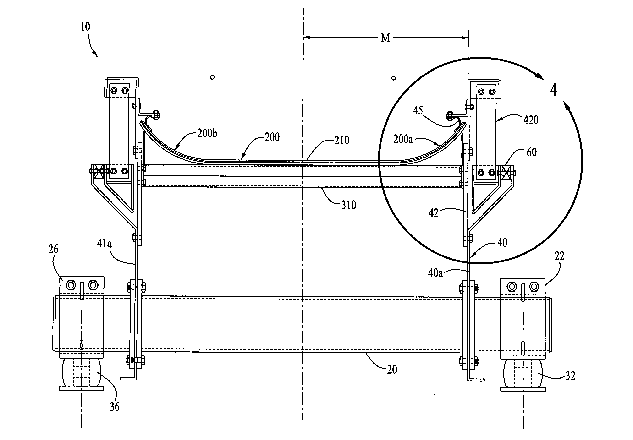
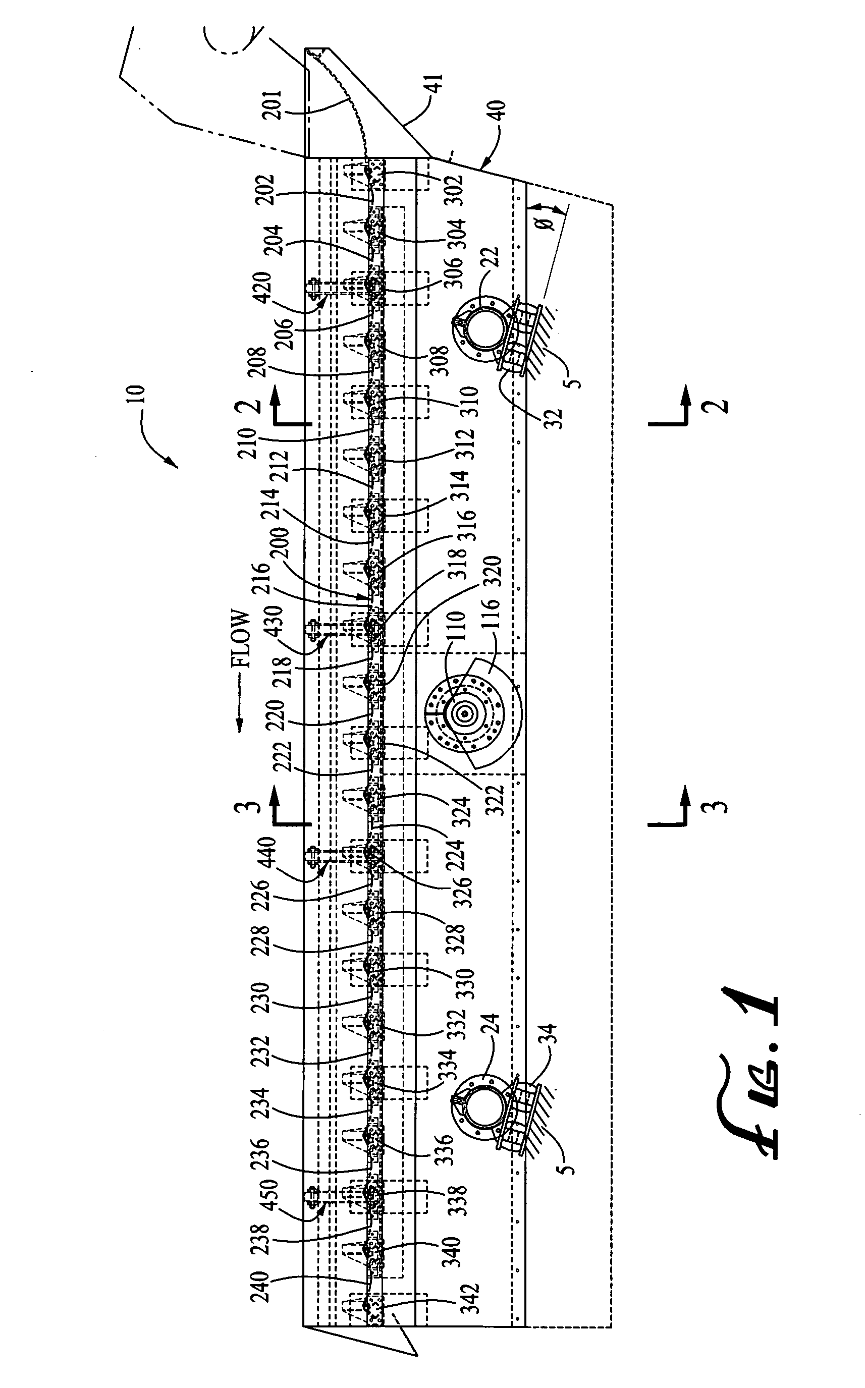
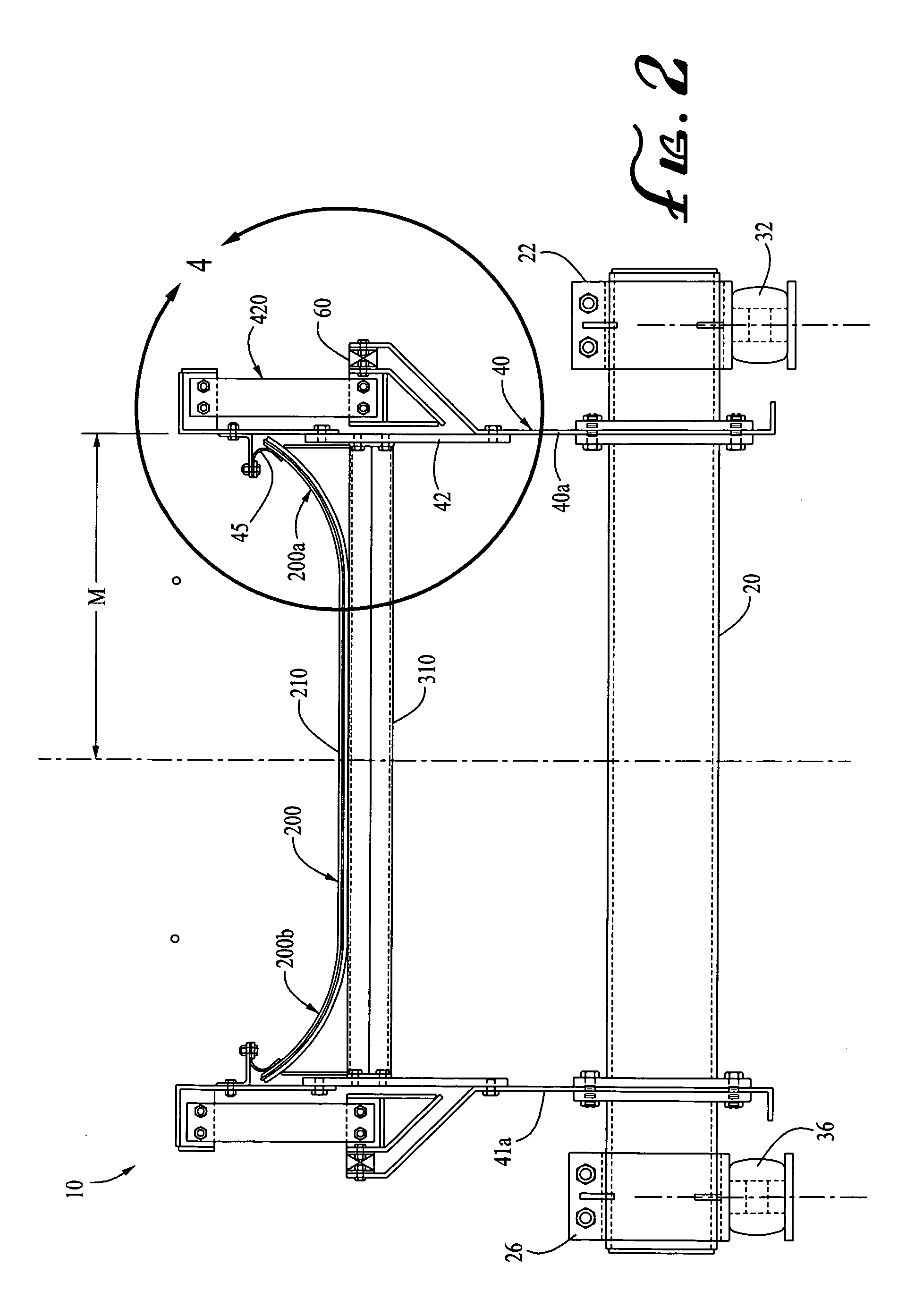
[0013] Preferred embodiments will now be described with reference to the drawings. To facilitate description, any element numeral representing an element in one figure will be used to represent the same element when used in any other figure.

[0014]FIGS. 1-5 illustrate a screening machine 10 according to a preferred embodiment. The screening machine 10 includes a first support frame section 40 which is supported on a foundation 5 or machine frame (not shown) via a plurality of mounts, each mount being supported on a corresponding isolation spring. The screening machine of FIG. 1 is illustrated with four mounts, but other suitable number of mounts may be implemented. The side elevation view of FIG. 1 shows mount 22 on isolation spring 32 and mount 24 on isolation spring 34. Though not visible in FIG. 1, the other pair of corresponding mounts and isolation springs are symmetrically disposed on the opposite side of the support frame 40. FIG. 2 illustrates mount 22 supported on isolation...


PUM


Abstract

Mechanical separators and screening machines, and methods for flexible sieve mat screening and flexible mat conveying are disclosed. In an example configuration, a flexible mat screening apparatus is provided with geometrically optimized guiding edge seals at lateral sides. One preferred configuration includes an assembly wherein a sieve mat has upwardly curved lateral sides forming a non-vertical, gradually curved shape. In another configuration, a movable support section is supported on a main frame section via a plurality of shear blocks, each arranged with its compression axis disposed horizontally. In yet another configuration, the movable support section is further connected to the main frame section via vertical stabilizers or leaf springs, the vertical stabilizers permitting longitudinal movement between the movable support section and the main frame section, but inhibiting vertical and/or lateral movement therebetween.

Description

BACKGROUND OF THE INVENTION [0001] The field of the present invention relates to vibratory screening machines and conveyors using flexible mats. [0002] Various designs have been proposed for sieve mat screening machines. For example, prior art screening machines have consisted of an elongated support frame with a mobile, deformable sieve mat, typically comprised of a plurality of sieve mat sections and having lateral edges extending in the direction of the length of the support frame in a series of alternating immobile and mobile sieve mat carriers mounted on the support frame and extending transversely along the length thereof, the sieve mat sections being affixed to the carriers with the mobile carriers being movable with respect to the support frame in the direction of the length of the support frame. During cycling of the screening machine, the individual screen mat sections are alternately tensioned and relaxed. The screening machine has a flat sieve mat with seals between the ...

Claims


Application Information

Patent Timeline
Patent Type & Authority Applications(United States)
IPC IPC(8): B07B1/28B07B1/46B07B1/48B07B1/49
CPCB07B1/46B07B1/4609B07B1/4654B07B1/485
Inventor LAVEINE, ANDREW T.HUMISTON, STANLEY L.
Owner ACTION EQUIP CO INC
Why Eureka
Try Eureka