
Liquid sensor and ice detector

a liquid sensor and detector technology, applied in liquid/fluent solid measurement, instruments, machines/engines, etc., can solve the problems of measuring reliably, requiring engine oil viscosity degradation, and devices susceptible to outside electrical and magnetic noise, so as to achieve the effect of reducing the cost of operation

Inactive Publication Date: 2005-06-16
MAATUK JOSEF
View PDF4 Cites 81 Cited by
  • Summary
  • Abstract
  • Description
  • Claims
  • Application Information

AI Technical Summary

Benefits of technology

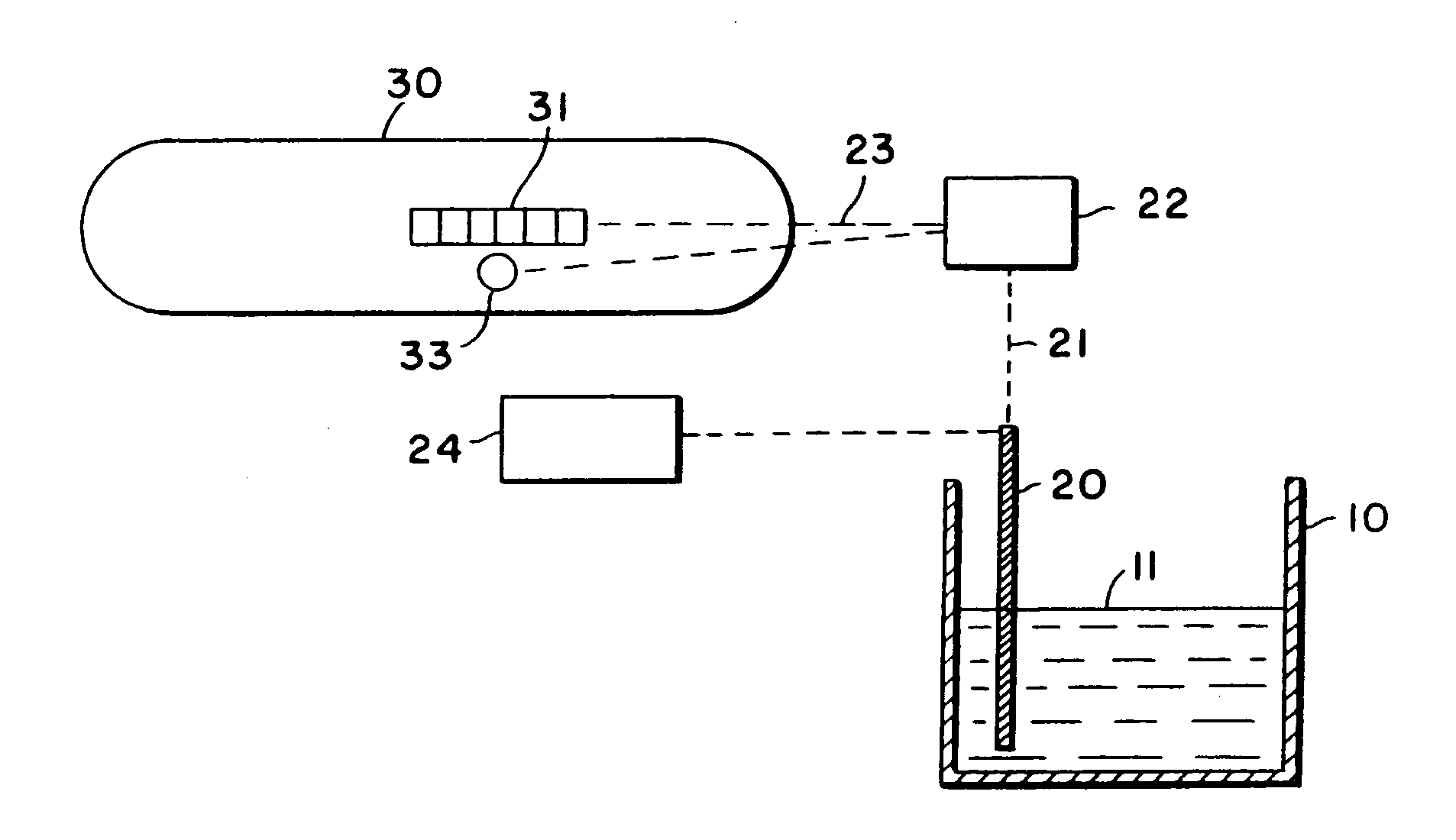
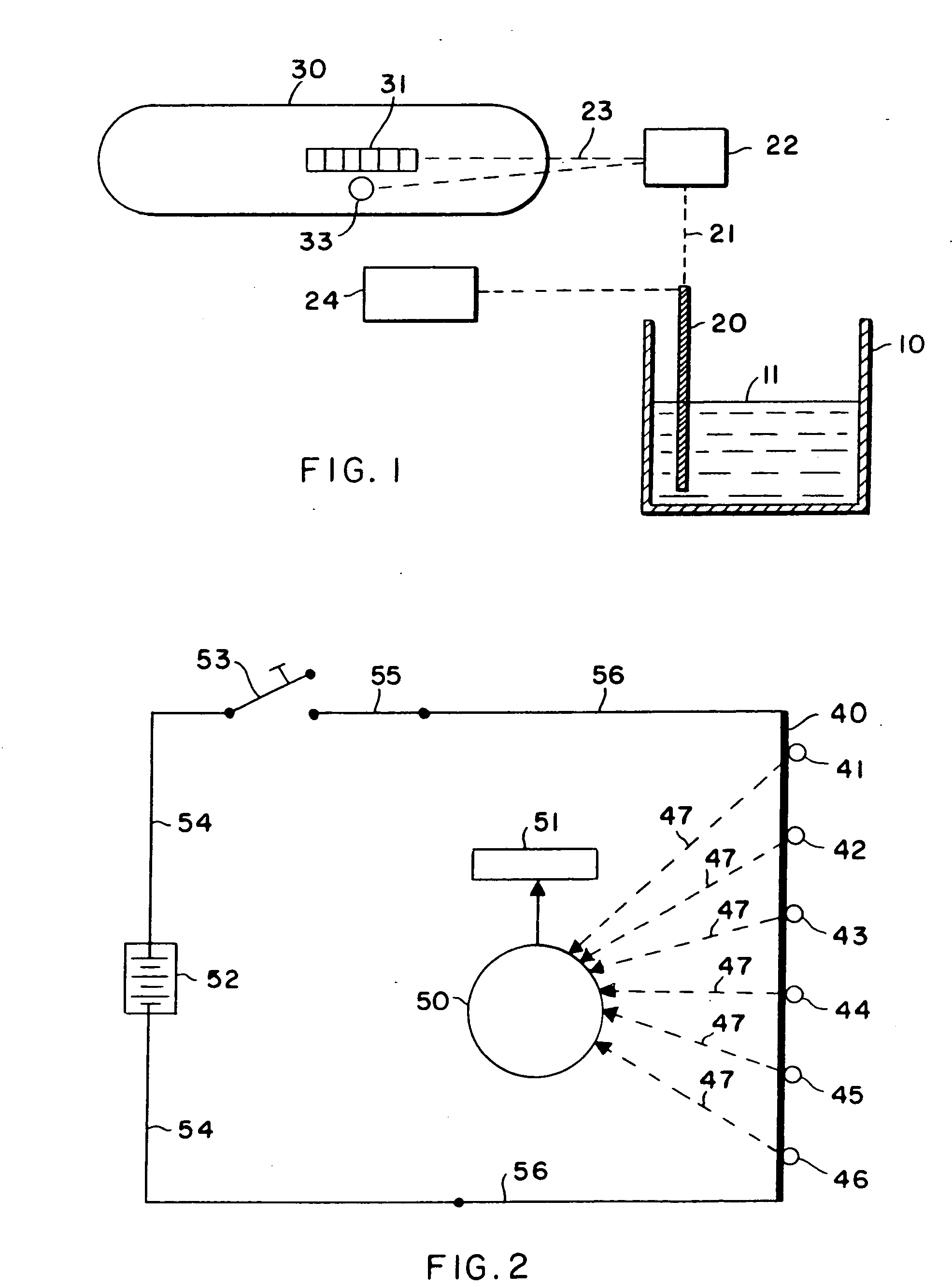
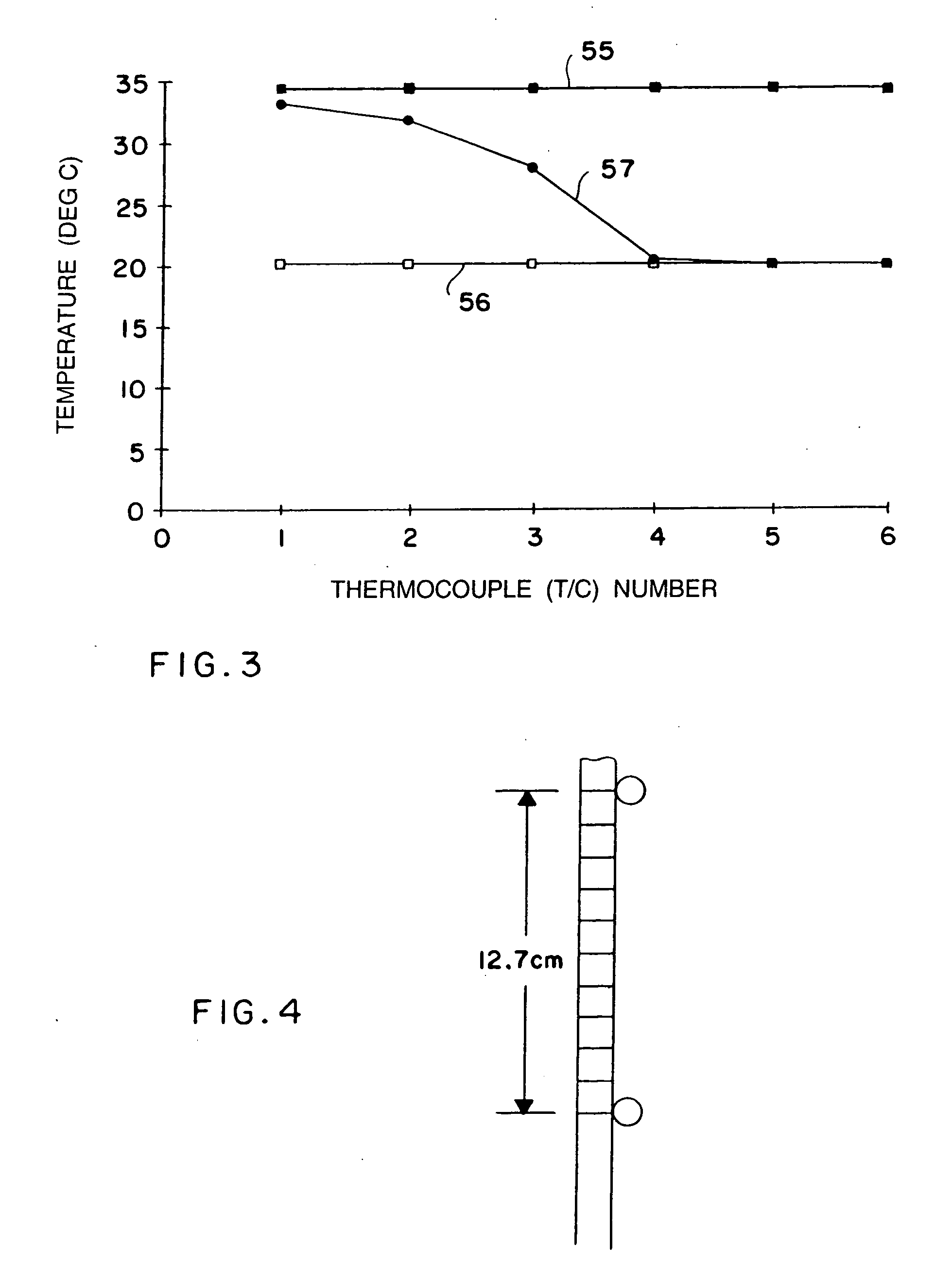
[0011] The invention described herein is a means of measuring the level of a liquid in a liquid container such as a fuel tank by means of a probe to which heat is applied and the temperature along the length of the probe is measured. This invention makes use of the difference in cooling efficiency between liquid and gas such as air, or between two different liquids, such as water and oil. When heat is applied to the probe, the temperature of the portion of the probe submerged in liquid is significantly lower than the temperature of that portion of the probe outside of the liquid and typically exposed to air. This is because the liquid removes heat at faster rate than air, so that the temperature difference between the surface of the probe is much lower in liquid than it is in air. This is also true between a liquid that removes heat more efficiently, such as water, and a liquid that does not remove heat as efficiently, such as oil. Temperature sensors, such as thermocouples or thermistors that are attached to various points on the probe to measure the temperatures at those respective locations on the probe. This invention is not only capable of determining accurately where the liquid level is at discrete points where the temperature sensors are attached. It can also determine where the liquid level is between two discrete points to within a fraction of centimeter accuracy, when precision temperature measurement devices and electronic circuitry are used in conjunction with suitable microprocessor, which collects and process the signals received from the temperature sensors.

Problems solved by technology

Moreover, the engine oil viscosity degradation is required too.
Furthermore, the monitoring of the health of the sensor operation and its hardware, will require maintenance only when the sensor fails or its performance is degraded below an acceptable low threshold level of accuracy.
Most of those devices are susceptible to outside electrical and magnetic noises.
Another limitation of the device described in U.S. Pat. No. 6,546,796 B2 is the fact that it can measure reliably the continuous liquid level only when linear thermocouples are used.

Method used


Image

  • Liquid sensor and ice detector
  • Liquid sensor and ice detector
  • Liquid sensor and ice detector

Examples


Embodiment Construction

[0028] The present invention describes a new method and a new sensor that measure accurately the liquid level, absolute temperature, viscosity degradation and density and pressure of compressible fluid in a three dimensional liquid container. The method requires the development and use of a profile or a mode shape along an axis. The profile has three components. First, a horizontal line for the section of the sensor that is in liquid. Second, a horizontal line for the sensor section that is in the medium above the liquid. Third, a curved line that connects the two horizontal line. This curved line can be viewed as a wave shape. The curved line length is a fraction of the height of the liquid container. The point of intersection between the wave and the first horizontal line tracks the motion of the liquid level. The height of the first horizontal line, height of the second horizontal line or the changes in the slope and curvature of the curved line are used to determine accurately t...


PUM


Abstract

An improved apparatus and a method of measuring and interpreting reliably, simply and accurately the information on continuous liquid level, liquid temperature and other liquid properties within a vessel. The apparatus could be made of a powered heater element and temperature sensors can be screen-printed, vacuum deposited, etched, welded, soldered or plated on one or both sides of a single rigid or a flexible substrate. The geometry of the heater determines the curve shape, such as steepness or shallowness of a temperature profile along a heater. Various parallel and serial configurations of thermocouples or temperature sensors can be used to measure the temperature along a heater. Simultaneous measurements from all the temperature sensors, before and after heat is applied, are used to generate accurate temperature profiles for the entire heater. Different features of the temperature profiles will determine accurately the liquid level, liquid temperature and other liquid properties. Apparatus of the invention may also be used to detect ice formation.

Description

REFERENCE CITED [0001]U.S. PATENT DOCUMENTS2279043April 1942Harrington073 / 2953279252October 1966Barlow073 / 2954969749November 1990Hasselman073 / 2952702476February 1955Boisblanc073 / 2953360990January 1968Greene073 / 2954785665November 1988McCulloch073 / 2954603580August 1986Waring073 / 2955521584May 1996Ortolano340 / 5814819480April 1989Sabin340 / 5814570230February 1986Wilson073 / 295X4573128February 1986Mazur073 / 295X6546796April 2003Zimmermann073 / 290R[0002]FOREIGN PATENT DOCUMENTS14926October 1991WO073 / 29544923March 1980Japan073 / 295158522September 1982Japan073 / 2956116January 1981Japan073 / 295281167October 1993Japan374 / 0162035154December 1977Germany374 / 016DESCRIPTION OF THE PRIOR ART [0003] The invention relates to methods and devices used to measure liquid level as well as temperature and other liquid parameters, within a vessel or container. The devices of this invention are made of a powered heater that can be used with various configurations of parallel and serial thermocouples or other tempera...

Claims


Application Information

Patent Timeline
IPC IPC(8): G01F23/00G01F23/24
CPCG01F23/247G01F23/246
Inventor MAATUK, JOSEF
Owner MAATUK JOSEF
Learn More