
Optical pickup system with light receiving portion

a technology of optical pickups and light receiving parts, applied in the field of optical pickups, can solve problems such as the likely deformation of the characteristic of hologram optical pickups, and achieve the effect of reducing the degradation of a characteristic and diffraction efficiency differences

Inactive Publication Date: 2006-03-21
SHARP KK
View PDF11 Cites 0 Cited by
  • Summary
  • Abstract
  • Description
  • Claims
  • Application Information

AI Technical Summary

Benefits of technology

[0021]Thus, the invention described herein makes possible the advantages of providing an optical pickup in which the difference in diffraction efficiency between reflected light beams passing through two regions provided in a hologram is reduced so as to reduce the degradation of a characteristic of a tracking error signal TES.

Problems solved by technology

As a result, the optical intensities of reflected light beams entering the optical detectors D1 to D5 are unbalanced, so that offset develops in the tracking error signal TES.
In this case, characteristics of the hologram optical pickup are likely to be degraded.

Method used


Image

  • Optical pickup system with light receiving portion
  • Optical pickup system with light receiving portion
  • Optical pickup system with light receiving portion

Examples


Embodiment Construction

[0030]Hereinafter, the present invention will be described by way of illustrative examples with reference to the accompanying drawings.

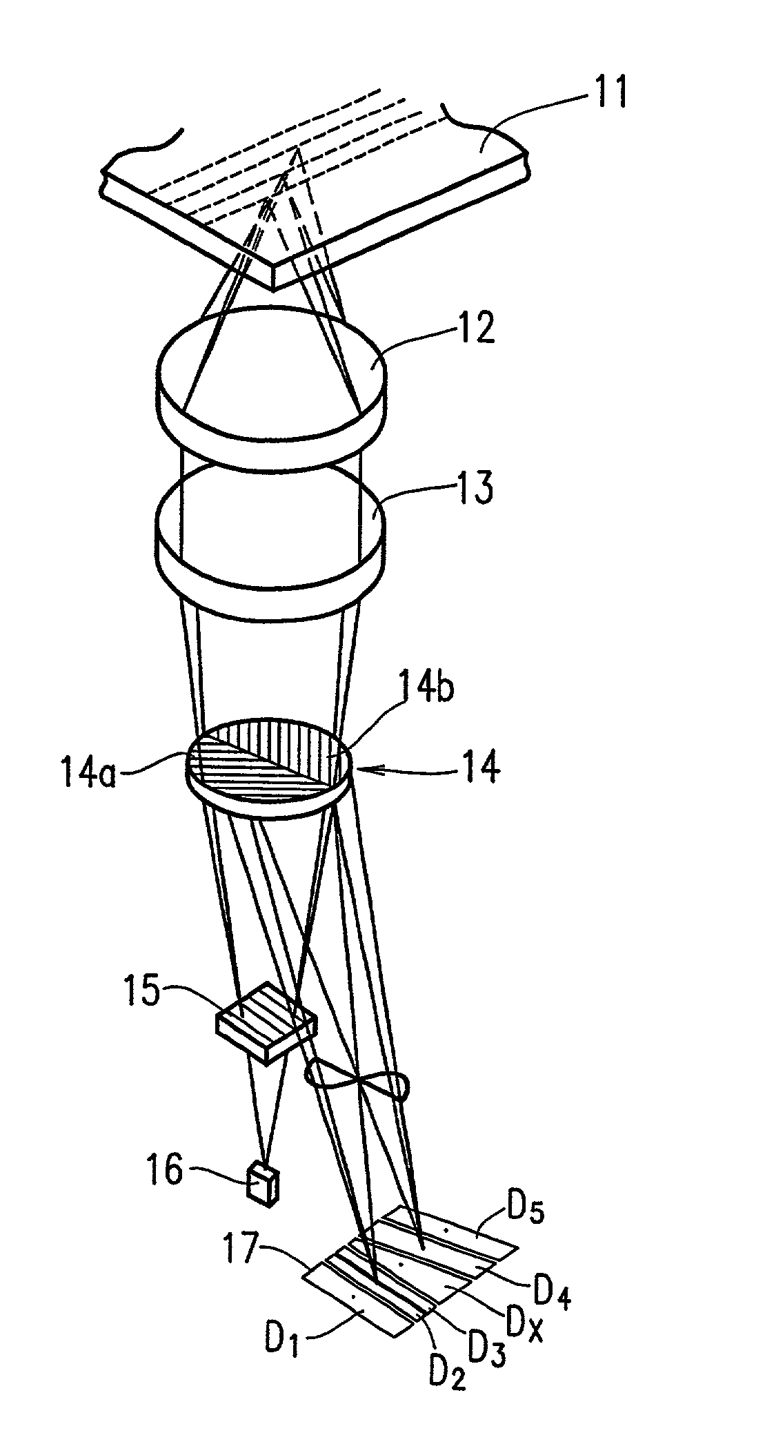
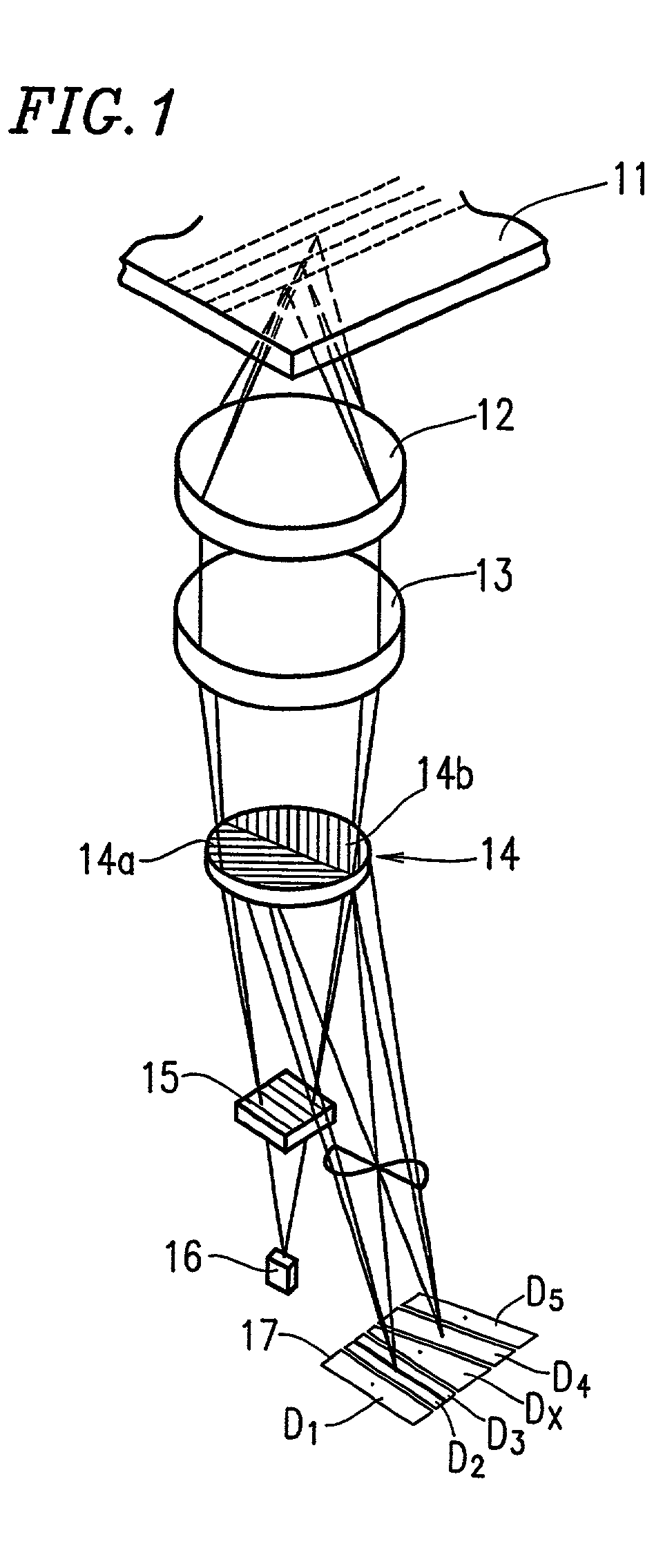
[0031]FIG. 1 is a schematic diagram showing the optical system of an optical pickup according to the present invention.

[0032]This optical pickup comprises a semiconductor laser chip 16 which emits predetermined light. Light emitted from the semiconductor laser chip 16 is split by a tracking beam generating diffraction grating 15 provided on the rear side of a hologram element (not shown) into three beams, i.e., two subbeams for tracking and one main beam for reading information signals. Those three light beams pass through a hologram 14 provided on the hologram element as zero-order light, and are then converted by a collimator lens 13 into parallel light. The parallel light is condensed by an objective lens 12 onto a disk 11. The light condensed onto the disk 11 is modulated by pits formed on the disk 11 and reflected from the disk 11. The reflected...


PUM

PropertyMeasurementUnit
distanceaaaaaaaaaa
lengthaaaaaaaaaa
widthaaaaaaaaaa

Abstract

An optical pickup comprises a light source, a three-way split light diffracting section for dividing light emitted from a light source into one main beam and two subbeams, a hologram for dividing each of the main beam and the subbeams reflected from a recording medium into two predetermined directions, and a light receiving section for receiving the beams divided by the hologram. The hologram includes two regions having a small-pitch grating for diffracting each beam to a predetermined direction, the small-pitch gratings have substantially the same pitch and are symmetrical about a split line separating the two regions.

Description

BACKGROUND OF THE INVENTION[0001]1. Field of the Invention[0002]The present invention relates to an optical pickup used in an optical disk system, such as a compact disk, a video disk, etc. More particularly, the present invention relates to an optical pickup comprising a hologram element-incorporating semiconductor laser device.[0003]2. Description of the Related Art[0004]An optical pickup comprising a semiconductor laser device is used to read out information stored in an optical disk, such as a compact disk, etc. In the optical pickup, light emitted from the semiconductor laser device is split by a diffraction grating of a hologram element into one main beam and two subbeams (tracking beams) which are brought onto an optical disk. The main beam and the subbeams are reflected on the optical disk, and each reflected beam is further split by a hologram of the hologram element into two beams, which are brought to a light receiving element or a signal processing integrated circuit wit...

Claims


Application Information

Patent Timeline
Patent Type & Authority Patents(United States)
IPC IPC(8): G11B7/13G11B7/09G11B7/12G11B7/123G11B7/131G11B7/133G11B7/135G11B7/1353
CPCG11B7/123G11B7/1353G11B7/133G11B7/131
Inventor HAMAOKA, OSAMU
Owner SHARP KK
Learn More