

Method and apparatus to improve analytical method development and sample preparation for reproducible particle size measurement
a particle size measurement and sample preparation technology, applied in the field of methods and apparatus to improve the preparation of sample samples for particle size measurement, can solve the problems of unresolved particle size measurement precision problems, analytical laboratories from independently verifying, and observed variations in measurement precision, etc., to achieve the effect of reducing the deviation of results, reducing power consumption, and reducing the life of ultra-sound probes
- Summary
- Abstract
- Description
- Claims
- Application Information
AI Technical Summary
Benefits of technology
Problems solved by technology
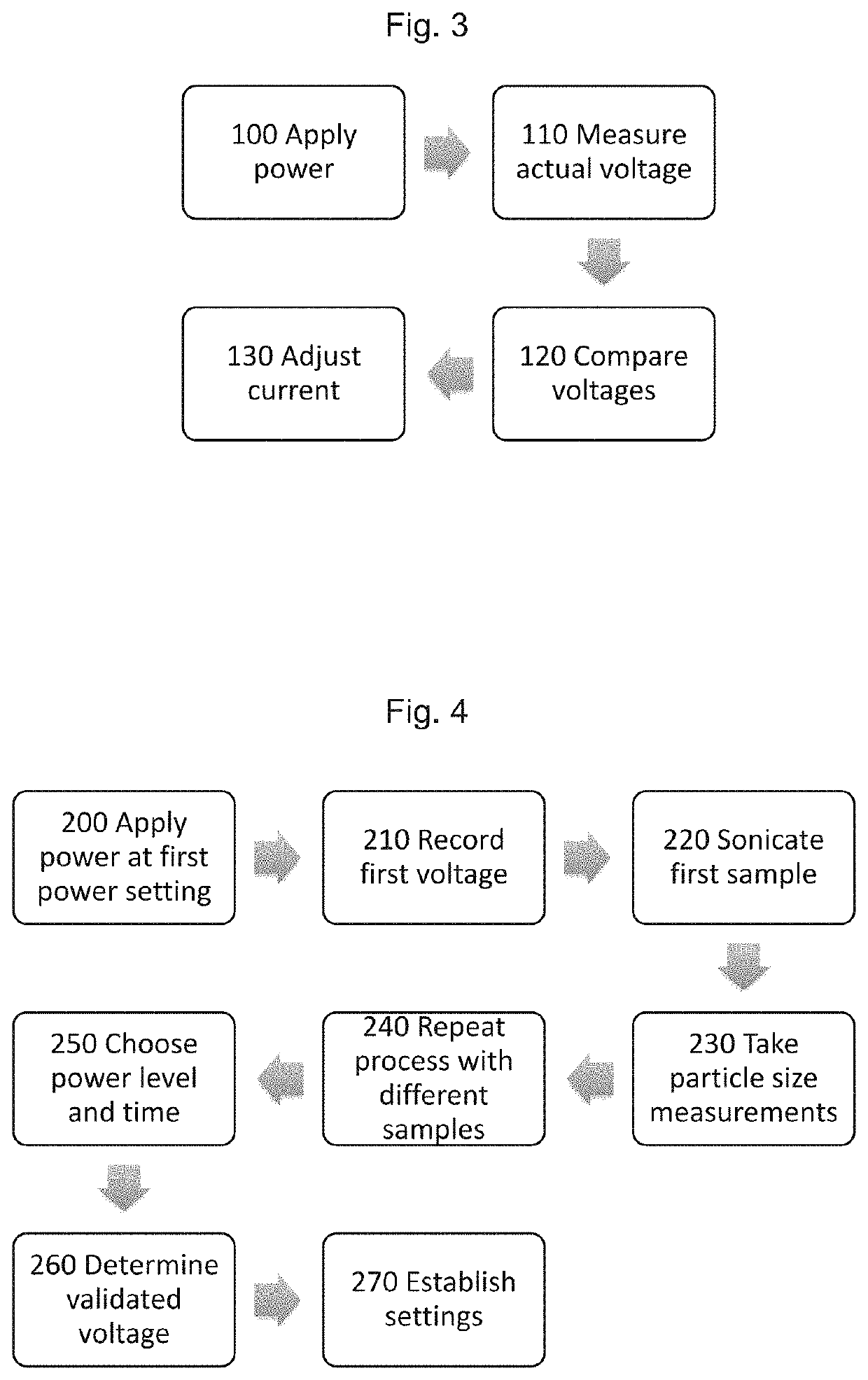
Method used
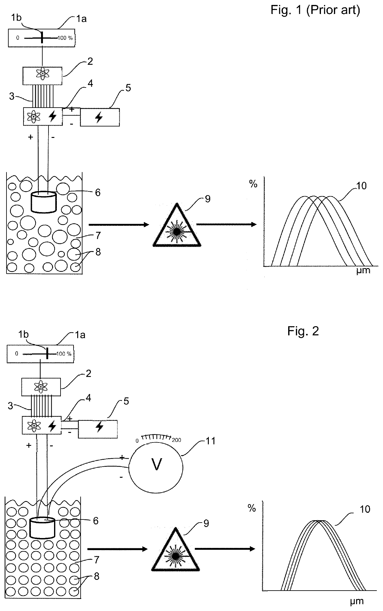
Image

Examples
example 1
[0067]The method of the present invention was tested in five different laser diffraction machines, being Malvern Mastersizer 2000 and Mastersizer 3000 machines manufactured by Malvern Instruments Ltd (Malvern, United Kingdom). The Malvern Mastersizer 3000 was also used in Mastersizer 2000 mode, so six sets of data were obtained. Each of the machines had its own built-in ultra-sound bath, with ultra-sound probes of varying ages, and they were used to sonicate the samples prior to testing.
[0068]The same batch of a pulmonary inhalation drug product was used for the testing, and this batch was obtained using a validated manufacturing process of wet polishing yielding the highest particle size precision and reproducibility. When observed by optical microscopy, these particles had similar physical and size characteristics.
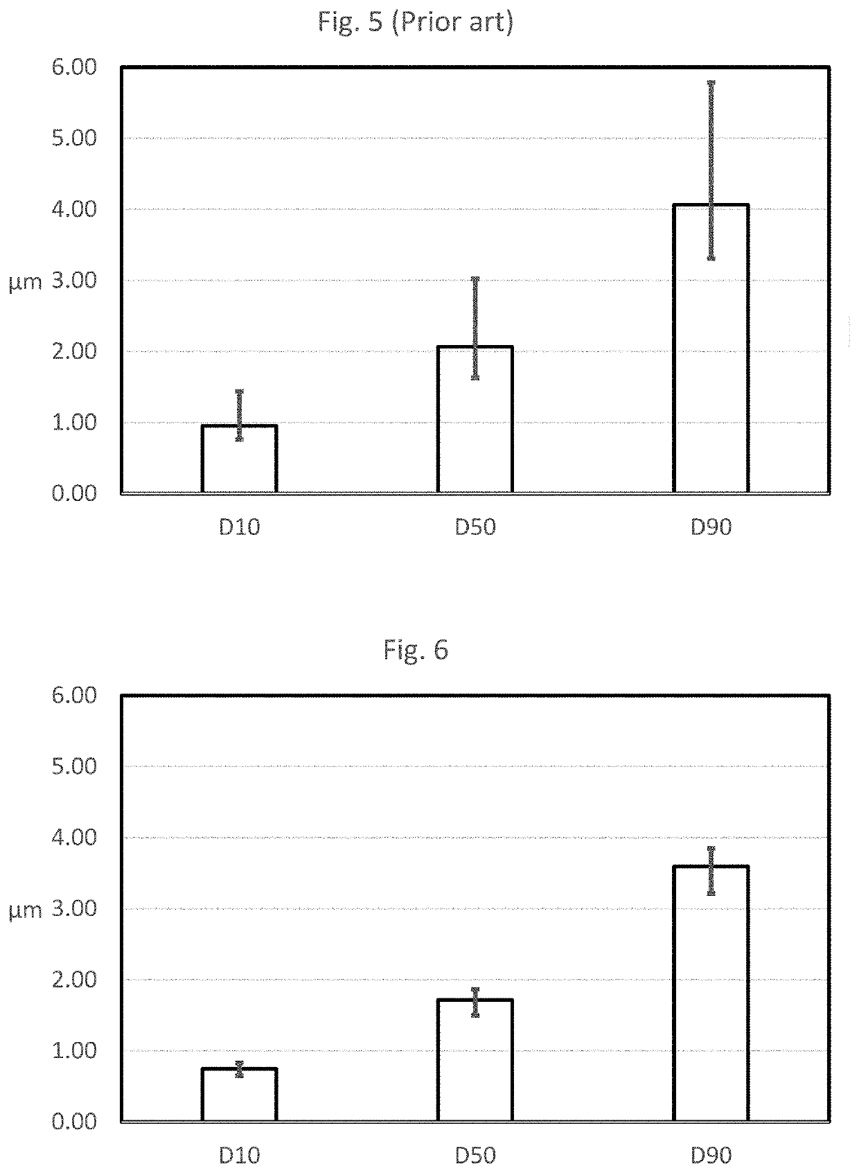
[0069]Table 1 below contains the results obtained using the method of the prior art, with the power level of the ultra-sound probe being set conventionally with a percen...
example 2
[0085]The experiments of Example 1 were repeated to test a different compound, using four laser diffraction machines. The methods were the same—prior art and inventive methods.
[0086]The same batch of an undisclosed drug product was used for the testing, and this batch was obtained using a validated manufacturing process of a size reduction process yielding known particle size precision and reproducibility. When observed by optical microscopy, these particles had similar physical and size characteristics.
[0087]Table 3 below contains the results obtained using the method of the prior art, with the power level of the ultra-sound probe being set conventionally with a percent scale of maximum power. Table 4 contains the results obtained using the improved method of the present invention.
[0088]The drug product was tested in all machines following the conventional method where power is set at the same value in the percentage power scale of the controller. Samples of the same drug product b...
example 3
[0101]The sonication performance of a new ultra-sound probe was compared with the sonication performance of an ultra-sound probe of undetermined age.
[0102]Two different batches of the same pharmaceutical drug product were tested. First, the samples were sonicated using an ultra-sound probe of undetermined age and tested by laser diffraction using a Malvern Mastersizer 2000 machine (CM02). Then, samples of the same two batches were sonicated using a new ultra-sound probe, in a different Malvern Mastersizer 2000 (CMOS) but no power adjustment was applied. Finally, the samples were tested again in CMOS, but this time the power of the new ultra-sound probe was adjusted so that the resulting voltage would match the voltage obtained in the first sonication and test of each of the batches. The particle size (PS) data is in tables 5 and 6.
[0103]
TABLE 5%ProbeD10D50D90EquipmentPowerEnergy [V](μm)(μm)(μm)Mastersizer 2000 - CM0220%44 V9.86235.56176.775with probe ofundetermined old ageMastersize...
PUM
| Property | Measurement | Unit |
|---|---|---|
| particle size | aaaaa | aaaaa |
| particle size | aaaaa | aaaaa |
| particle size | aaaaa | aaaaa |
Abstract
Description
Claims
Application Information