
Heat exchange device and closed-type electronic apparatus using the same

a technology of electronic equipment and heat exchange device, which is applied in the direction of electrical equipment casings/cabinets/drawers, ventilation systems, instruments, etc., can solve the problems of reducing reliability and lifetime, affecting the reliability of electronic products, and affecting the stability of electronic products, so as to prevent water leaking through the external circulating fan, simplify the wiring, and expand the surface area

Active Publication Date: 2011-05-26
DELTA ELECTRONICS INC
View PDF68 Cites 1 Cited by
  • Summary
  • Abstract
  • Description
  • Claims
  • Application Information

AI Technical Summary

Benefits of technology

[0010]In view of the foregoing, the present invention is to provide a heat exchange device which can be easily maintained, simplify the complexity of wiring, and prevent the damage caused by water leaking in through the external circulating fan, and a closed-type electronic apparatus using the heat exchange device.
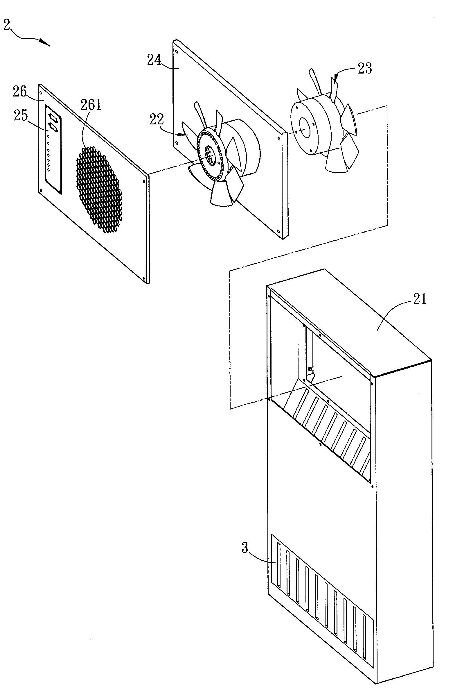
[0021]In summary, the internal circulating fan and the external circulating fan of the heat exchange device in accordance with the present invention are disposed at the same side relative to the heat exchange unit. In other words, because both the internal circulating fan and the external circulating fan can be disposed in the top of the heat exchange device, the heat exchange device of the present invention can prevent the damage caused by water leaking through the external circulating fan. In addition, the wiring configurations such as the control circuit and the power wire can avoid passing through the heat exchange unit due to that the internal circulating fan and the external circulating fan are disposed at the same side relative to the heat exchange unit, so that the complexity of wiring can be simplified. Moreover, when the internal circulating fan and the external circulating fan require maintenance, users just have to remove the cover at one side and then can execute the maintenance on both the internal circulating fan and the external circulating fan, simultaneously. It is more convenient for maintaining the heat exchange device of the present invention.
[0022]In addition, the heat exchange unit of the heat exchange device in accordance with the present invention can include two inclined surfaces corresponding to the internal circulating fan and the external circulating fan, respectively, and the inlets of the internal circulating void layers and the inlets or outlets of the external circulating void layers are disposed on the different inclined surfaces, respectively. Therefore, this configuration can expand the surface area of the vents and thereby increases the amounts of the inward and outward air flows. Consequentially, it promotes the efficiency of the heat dissipation of the heat exchange device in accordance with the present invention.
[0023]Furthermore, since both the internal circulating fan and the external circulating fan are disposed at the same side relative to the heat exchange device, it promotes the efficiency of heat dissipation of the heat exchange device. Alternatively, the heat exchange device of the present invention can achieve the same level of the efficiency of heat dissipation with a smaller size.

Problems solved by technology

As electronic products progress in their performances, they generate more and more heat in operation resulting in temperature increase.
It severely jeopardizes the stability of the electronic products and, meanwhile, reduces their reliability and lifetime.
Thus, the heat dissipation has become an important issue for the electronic products.
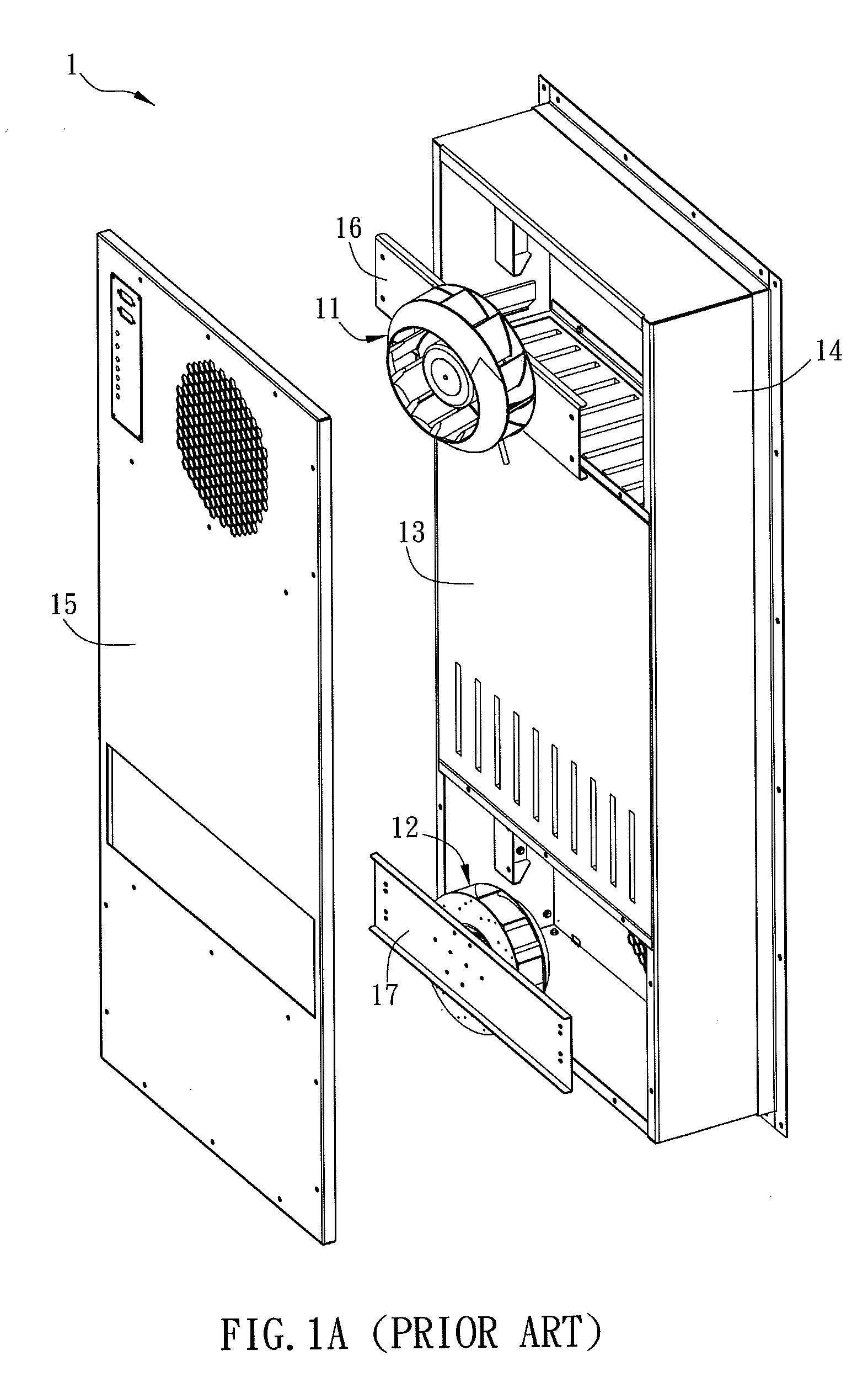
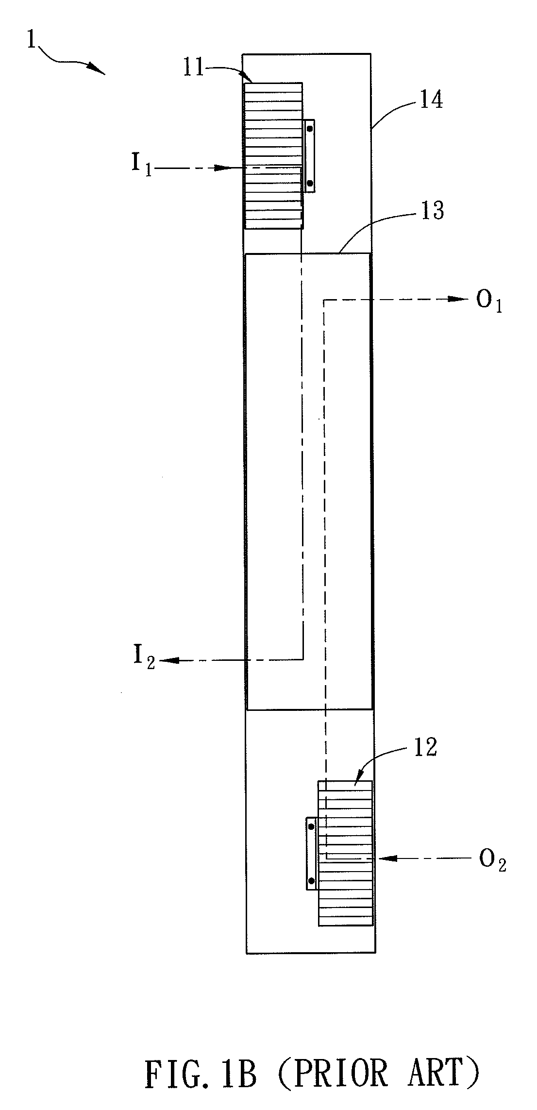
It damages the external circulating fan 12 and further results in the loss of the heat dissipation function of the heat exchange device 1.
This is inconvenient for wiring.
Additionally, the internal circulating fan 11 and the external circulating fan 12 are disposed on different fixing seats 16 and 17, respectively, which results in the increase of material cost.
It is inconvenient for maintenance as well.

Method used


Image

  • Heat exchange device and closed-type electronic apparatus using the same
  • Heat exchange device and closed-type electronic apparatus using the same
  • Heat exchange device and closed-type electronic apparatus using the same

Examples


Embodiment Construction

[0033]The present invention will be apparent from the following detailed description, which proceeds with reference to the accompanying drawings, wherein the same references relate to the same elements.

[0034]FIG. 2A is a laterally cross-sectional figure of a closed-type electronic apparatus A of a preferred embodiment in accordance with the present invention, and FIG. 2B is a decomposition figure of a heat exchange device 2 of the preferred embodiment in accordance the present invention. The closed-type electronic apparatus A can be, for example, a server apparatus or other large closed-type electronic apparatuses.

[0035]As shown in FIG. 2A, the closed type apparatus A includes a housing A1, an electronic assembly A2 and a heat exchange device 2. The electronic assembly A2 is disposed in the housing A1. Because the electronic assembly A2 generates heat in operation, it is necessary to apply the heat exchange device 2 of the present invention to dissipate the undesired heat. To be not...


PUM


Abstract

A heat exchange device includes a housing, an internal circulating fan, an external circulating fan and a heat exchange unit. The internal and external circulating fans and the heat exchange unit are disposed in the housing. The internal and external circulating fans are disposed at the same side relative to the heat exchange unit. A closed-type electronic apparatus including the heat exchange device is also disclosed.

Description

CROSS REFERENCE TO RELATED APPLICATIONS[0001]This Non-provisional application claims priority under 35 U.S.C. §119(a) on Patent Application No(s). 098139633 filed in Taiwan, Republic of China on Nov. 20, 2009, the entire contents of which are hereby incorporated by reference.BACKGROUND OF THE INVENTION[0002]1. Field of Invention[0003]The present invention relates to a closed-type electronic apparatus and a heat exchange device thereof.[0004]2. Related Art[0005]As electronic products progress in their performances, they generate more and more heat in operation resulting in temperature increase. It severely jeopardizes the stability of the electronic products and, meanwhile, reduces their reliability and lifetime. Thus, the heat dissipation has become an important issue for the electronic products. Frequently, heat exchange devices are responsible to heat dissipation inside closed-type electronic apparatuses.[0006]FIG. 1A is a decomposition figure of a conventional heat exchange devic...

Claims


Application Information

Patent Timeline
Patent Type & Authority Applications(United States)
IPC IPC(8): H05K7/20F28F9/007
CPCF28D1/024F28D1/03H05K7/206H05K7/202F28D2021/0031
Inventor CHEN, LEE-LONGHUANG, CHIEN-HSIUNGTU, YA-SEN
Owner DELTA ELECTRONICS INC
Learn More