Auto sense and encode printer system for multiple classes of RFID tags

a printer system and rfid tag technology, applied in the field of printer systems, can solve the problems of unreadable rendering, inability to further modify, and many businesses or users may not have suitable rfid readers to read the rfid tag

Inactive Publication Date: 2005-12-15
PRINTRONIX INCORPORATED
View PDF10 Cites 43 Cited by
  • Summary
  • Abstract
  • Description
  • Claims
  • Application Information

AI Technical Summary

Benefits of technology

[0011] Accordingly, the printer system is able to encode and print to more than one class of RFID tag without making any hardware or software changes in the printer and with or wit

Problems solved by technology

In addition, bar code labels can become soiled in transit, rendering them unreadable.
Moreover, RFID tags may be written to in write-once or write-many fashions whereas once a bar code label has been printed furthe

Method used


Image

  • Auto sense and encode printer system for multiple classes of RFID tags
  • Auto sense and encode printer system for multiple classes of RFID tags
  • Auto sense and encode printer system for multiple classes of RFID tags

Examples


Embodiment Construction

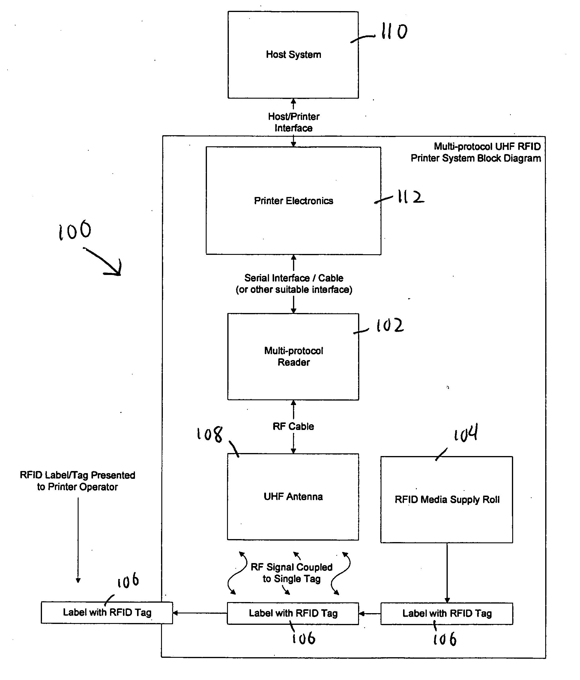
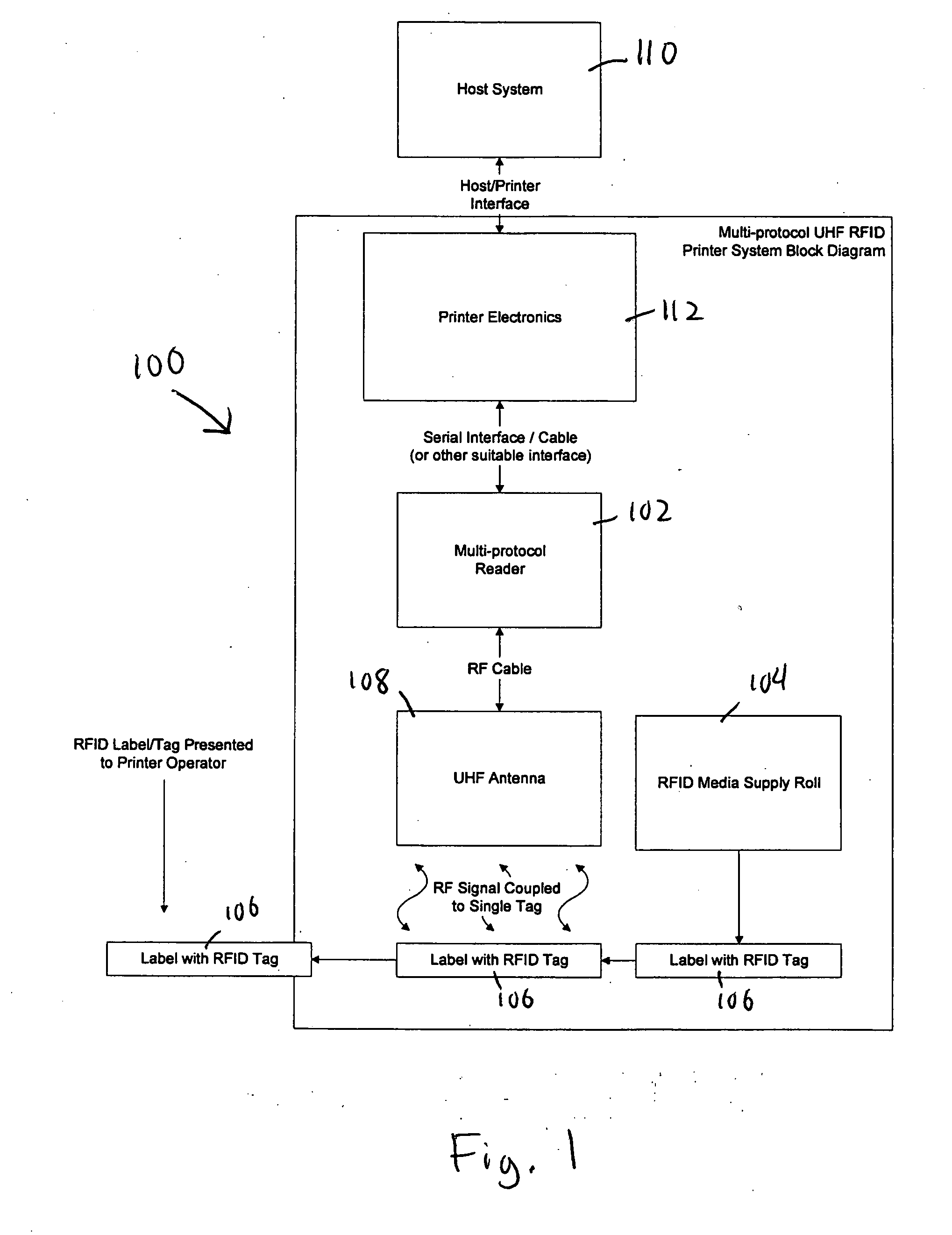
[0017]FIG. 1 is a block diagram of an exemplary radio frequency identification (RFID) printer system 100 with a multi-protocol reader 102 that may be used with the present invention. RFID printer system 100 also includes a roll 104 of labels 106 or media, where an RFID tag is embedded in each label 106. RFID tags are passive or active tags available from a multitude of manufacturers, including Alien Technology Corporation of Morgan Hill, Calif., Matrics, Inc. of Rockville, Md., and Philips Semiconductor of the Netherlands. Labels from roll 104 are fed past an RFID antenna 108, programmed or read, and printed by a thermal print head or other print mechanism. RFID antenna 108 is positioned with respect to the labels to enable efficient or optimized interrogation of the labels. A host computer 110 is coupled to printer electronics or a printer controller 112, such as through a host / printer interface. Note that host computer 110 is typically external to and not part of the printer syste...


PUM


Abstract

An RFID printer system and method interrogates or accesses RFID tags automatically using a user-defined sequence of settings for different RFID tags or classes. Once a successful interrogation is completed, the settings are saved and the saved settings are used for interrogation on the next tag. Each new roll of tags/labels starts interrogation with the first of the settings. Consequently, the printer system can read from and write to tags of more than one class without hardware or software changes in the printer.

Description

RELATED APPLICATION [0001] The present application is based on and claims priority to U.S. Provisional application Ser. No. 60 / 578,657, filed Jun. 9, 2004.BACKGROUND [0002] 1. Field of Invention [0003] The present invention relates generally to printer systems, and more particularly to RFID printer systems. [0004] 2. Related Art [0005] Radio Frequency Identification (RFID) systems represent the next step in automatic identification techniques started by the familiar bar code schemes. Whereas bar code systems require line-of-sight (LOS) contact between a scanner and the bar code being identified, RFID techniques do not require LOS contact. This is a critical distinction because bar code systems often need manual intervention to ensure LOS contact between a bar code label and the bar code scanner. In sharp contrast, RFID systems eliminate the need for manual alignment between an RFID tag and an RFID reader or interrogator, thereby keeping labor costs at a minimum. In addition, bar cod...

Claims


Application Information

Patent Timeline
IPC IPC(8): B41J3/44G06F3/12G06F17/00G06K17/00G07C9/00
CPCB41J3/407B41J3/44G06K7/10316G06K17/00G06K17/0025G07C9/00111G07C9/28
Inventor CHAPMAN, THEODORE A.EDWARDS, ANDREW W.
Owner PRINTRONIX INCORPORATED
Why Eureka
Try Eureka