
Independent measurement of complicated transfer functions

a technology of transfer function and independent measurement, which is applied in the direction of frequency analysis, speed/acceleration/shock measurement devices, testing/calibration of speed/acceleration/shock measurement devices, etc., can solve the problem that the network analyzer is not suitable for measuring the transfer function of a complex apparatus, and the measurement method using a known modulation signal is unrealisti

Inactive Publication Date: 2005-12-15
TEKTRONIX INT SALES GMBH
View PDF6 Cites 14 Cited by
  • Summary
  • Abstract
  • Description
  • Claims
  • Application Information

AI Technical Summary

Problems solved by technology

However, it is very difficult for the network analyzer to measure the frequency transfer function of a spectrum analyzer since the spectrum analyzer has down converters that make the measurement complicated.
As indicated above, the network analyzer is not suitable for measuring the transfer function of a complex apparatus, such as a spectrum analyzer having down converters.
The measurement method using a CW signal requires special measurement instruments and cannot measure a phase characteristic.
The measurement method using a known modulation signal is not realistic because the method requires an ideal modulation signal source.

Method used


Image

  • Independent measurement of complicated transfer functions
  • Independent measurement of complicated transfer functions
  • Independent measurement of complicated transfer functions

Examples


Embodiment Construction

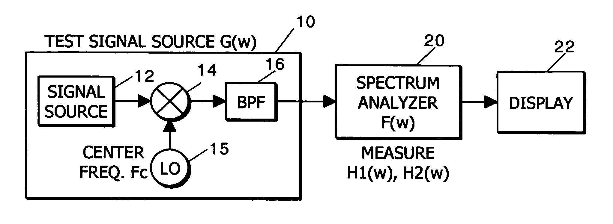
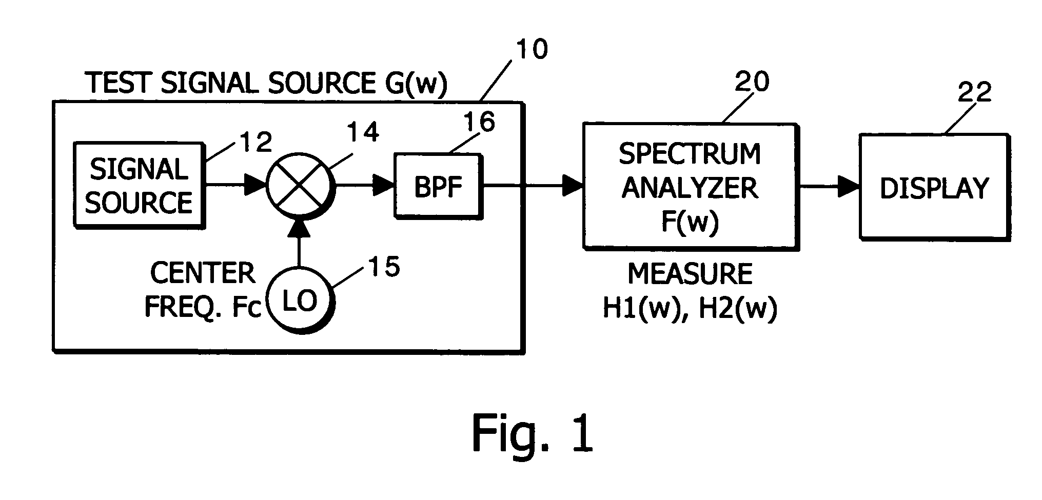
[0012] Referring now to FIG. 1, a test signal source 10 has characteristics indicated by a transfer function G(w), called for the purpose of explanation of the invention the “first transfer function.” A signal source 12 provides a known test signal to a mixer 14. The signal source 12 provides, for example, an OFDM (Orthogonal Frequency Division Multiplexing) signal that is derived by converting digital data into analog signals and modulating the analog signals by a plurality of signals of different frequencies. The OFDM signal is desirable because it has flat characteristics in the frequency domain. The mixer 14 mixes the test signal with a desired center frequency signal Fc from an oscillator 15. A band pass filter (BPF) 16 selectively outputs a signal having desired frequencies. This process provides a desired frequency shift to the test signal, as is well known. Although not shown, the test signal test signal source 10 may include an input device (keyboard, etc.) and a control de...


PUM


Abstract

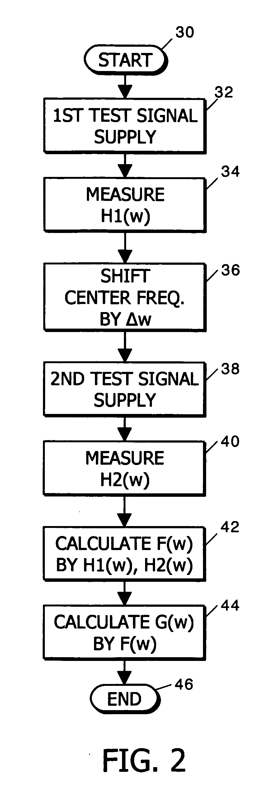
A first test signal from a test signal source is provided to a spectrum analyzer to produce first measurement data. The test signal source is expressed by a first transfer function G(w) and the spectrum analyzer is expressed by second transfer function F(w). A second test signal is provided to the spectrum analyzer to produce second measurement data where the second test signal is derived from the first test signal by shifting the frequency by a known increment. From the first and second measurement data, the components are the same on G(w) but different on F(w). The G(w) components are cancelled by calculation using the first and second measurement data and then the second transfer function F(w) is evaluated independently of G(w).

Description

BACKGROUND OF THE INVENTION [0001] The present invention relates to measuring a transfer function of a device, and more particularly to measuring the transfer function of a frequency analyzer independently from a transfer function for a test signal source. [0002] A network analyzer is used to measure frequency transfer functions of various circuits, such as filters, amplifiers, etc., by using two factors—amplitude and phase. However, it is very difficult for the network analyzer to measure the frequency transfer function of a spectrum analyzer since the spectrum analyzer has down converters that make the measurement complicated. [0003] Previously for measuring complicated transfer functions a first method provides an apparatus under test with a continuous wave (CW) signal as an input having known characteristics (amplitude and phase). A second method measures input and output signals of the apparatus under test to determine the characteristics, the input signal being a known continu...

Claims


Application Information

Patent Timeline
Patent Type & Authority Applications(United States)
IPC IPC(8): G01R27/28G01R23/16
CPCG01R23/16G01R27/28
Inventor YOSHIHARA, KOICHIMIYAKE, KENICHIAKITA, YONEO
Owner TEKTRONIX INT SALES GMBH
Learn More