Vehicle lighting system

a technology for vehicle lighting and lighting, which is applied in the direction of television systems, lighting and heating apparatus, instruments, etc., can solve the problem that the area other than the direction in which the vehicle is steered cannot be illuminated accurately according to the running conditions of the vehicl

Active Publication Date: 2005-12-15
KOITO MFG CO LTD
View PDF10 Cites 76 Cited by
  • Summary
  • Abstract
  • Description
  • Claims
  • Application Information

AI Technical Summary

Benefits of technology

[0016] In accordance with one or more embodiments of the present invention, the control unit may swing the illuminating direction of each of the plurality of light sources, so that a boundary between adjacent illumination areas is illuminated.

Problems solved by technology

In the technique, however, areas other than an area in the direction in which the vehicle is steered cannot be illuminated accurately according to the running conditions of the vehicle.

Method used


Image

  • Vehicle lighting system
  • Vehicle lighting system
  • Vehicle lighting system

Examples


Embodiment Construction

[0044] While the invention will be described through an embodiment of the invention below, an embodiment described below is not such as to limit an invention claimed, and all possible combinations of features that will be described in the embodiment will not constitute inevitable means for attaining the invention.

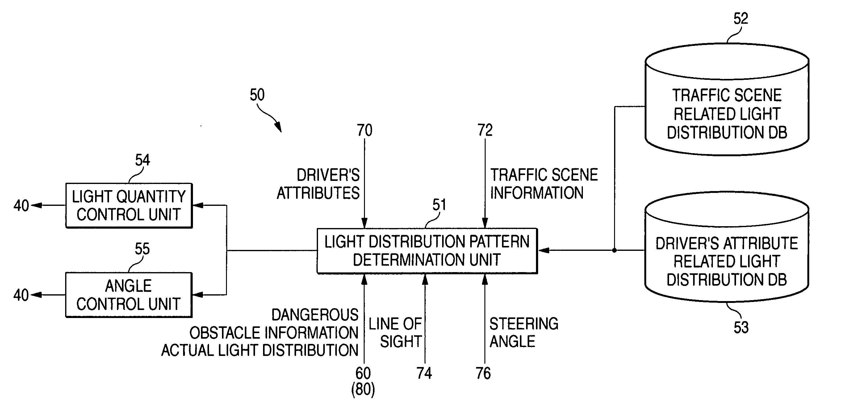
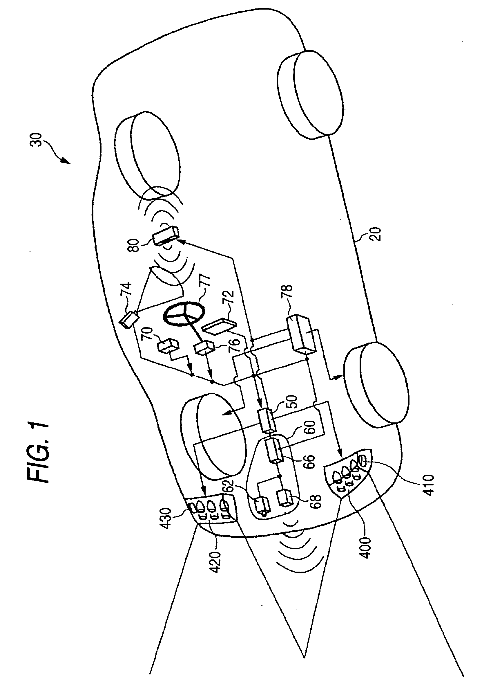
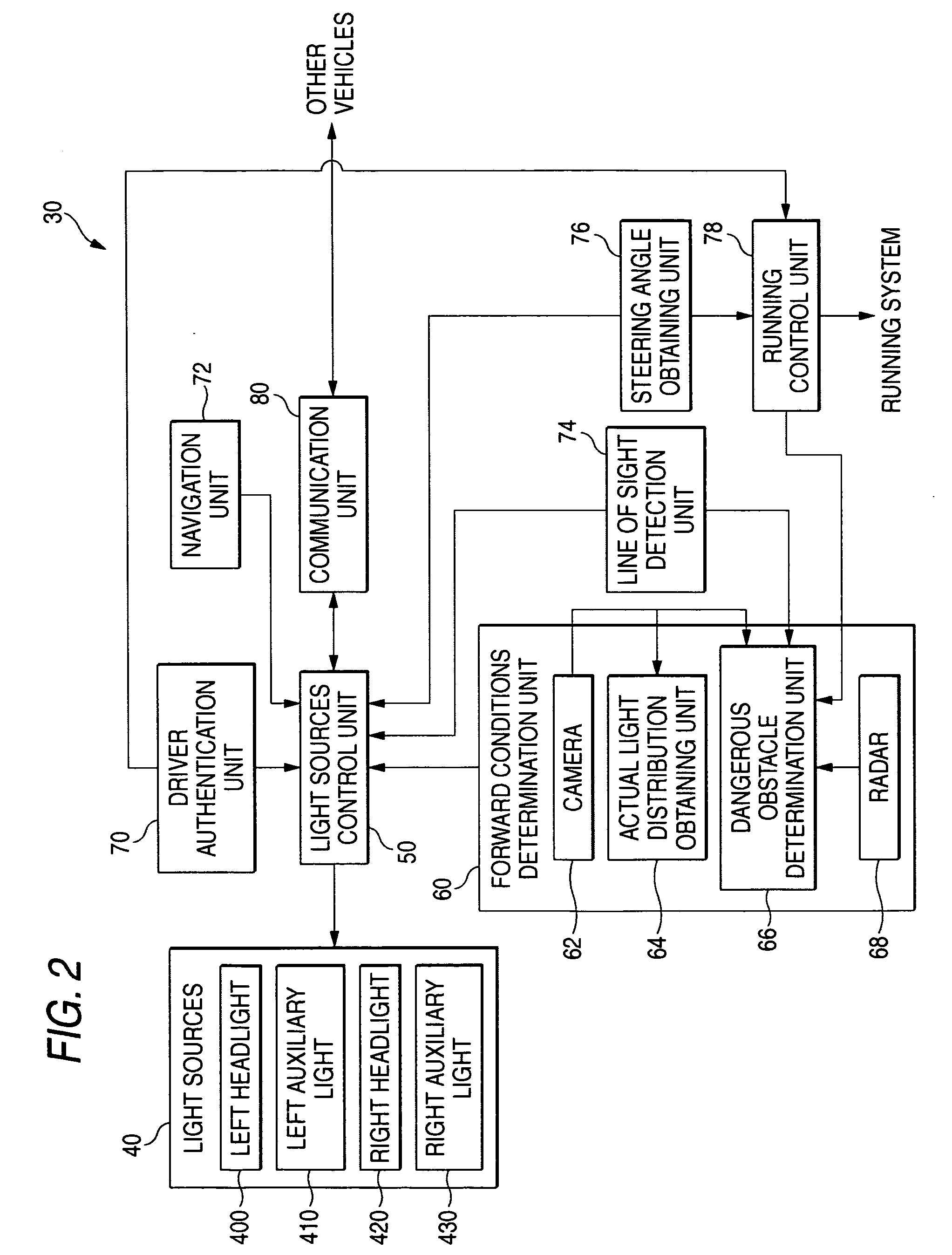
[0045]FIGS. 1 and 2 illustrate the configuration of a vehicle lighting system 30 according to an embodiment of the invention. FIG. 1 shows a conceptual layout of the vehicle lighting system 30 installed on a vehicle 20. FIG. 2 shows a functional configuration of the vehicle lighting system 30 in the form of a block diagram. The vehicle lighting system 30 according to the embodiment is intended to make the driver feel safe and to improve the running safety by controlling the illumination according to the environment and state in which the vehicle 20 is driven and the state of the driver.

[0046] The vehicle lighting system 30 includes a plurality of light sources 40, a forwa...


PUM


Abstract

A vehicle lighting system for illuminating ahead of a vehicle is provided with a plurality of light sources each adapted to illuminate a different illumination area to thereby form a predetermined light distribution pattern as a whole and a control unit for determining a traffic scene in which the vehicle is running and independently changing at least either an orientations or the light quantities of the plurality of light sources so as to form a target light distribution pattern which has been set in advance for the traffic scene.

Description

[0001] The present application claims foreign priority based on Japanese Patent Application No. P.2004-174475, filed on Jun. 11, 2004, the contents of which are incorporated herein by reference. BACKGROUND OF THE INVENTION [0002] 1. Field of the Invention [0003] The present invention relates to a vehicle lighting system, and more particularly, the invention relates to a vehicle lighting system which changes the forward illumination during running. [0004] 2. Related Art [0005] JP-A-2001-325817 discloses a technique for illuminating a direction in which an automotive vehicle turns by directing light sources of headlamps of the automotive vehicle towards the direction in which the vehicle is steered to make such a turn. [0006] In the technique, however, areas other than an area in the direction in which the vehicle is steered cannot be illuminated accurately according to the running conditions of the vehicle. SUMMARY OF THE INVENTION [0007] In accordance with one or more embodiments of...

Claims


Application Information

Patent Timeline
Patent Type & Authority Applications(United States)
IPC IPC(8): F21S8/10B60Q1/08B60Q1/12B60Q1/18F21V14/02F21W101/10F21W107/10G08G1/01
CPCB60Q1/085F21S48/171B60Q2300/054B60Q2300/056B60Q2300/112B60Q2300/116B60Q2300/122B60Q2300/23B60Q2300/312B60Q2300/322B60Q2300/331B60Q2300/332B60Q2300/333B60Q2300/334B60Q2300/41B60Q2300/45B60Q1/18F21S41/62
Inventor WATANABE, TAKAO
Owner KOITO MFG CO LTD
Why Eureka
Try Eureka