Universal modular power supply carrier
a power supply carrier and universal technology, applied in the field of portable power supplies, can solve the problems of not meeting the combined size and electrical requirements of standard supplies, the development process is not fast, and the cost of custom-made power supplies is $30-50, so as to reduce the development time and cost
- Summary
- Abstract
- Description
- Claims
- Application Information
AI Technical Summary
Benefits of technology
Problems solved by technology
Method used
Image

Examples
embodiment 200
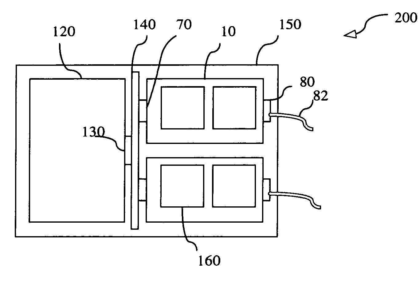
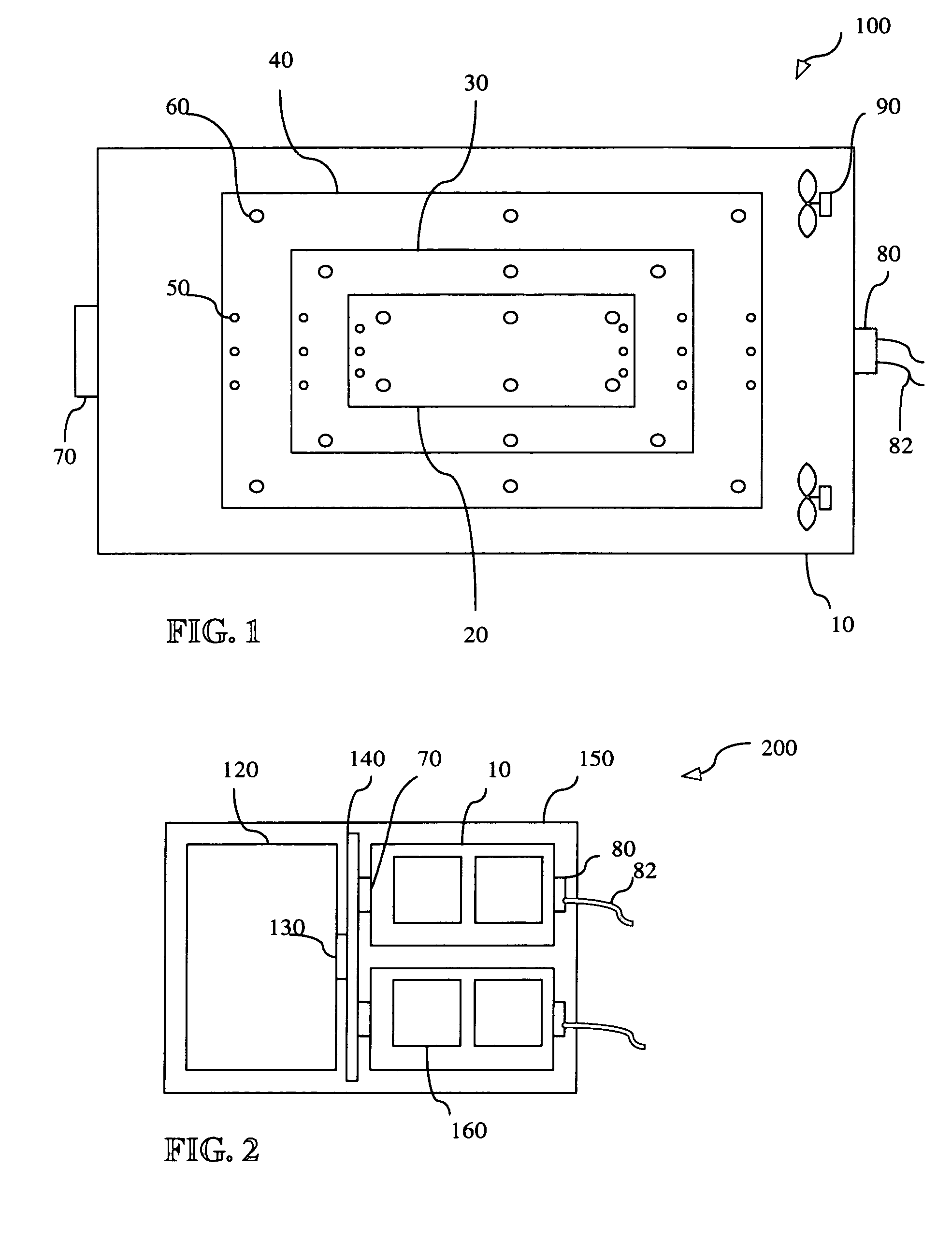
[0028]FIG. 2 shows a cabinet 150 using the universal modular power supply carrier 10 of the present invention. In this embodiment 200, two universal modular power supply carriers 10 are shown mounted within a cabinet 150. Each universal modular power supply carrier 10 has two power supplies or power assemblies 160. An alternating current, or direct current, power cord 82 attaches to the universal modular power supply carriers through a receptacle 80. The universal modular power supply carriers attach to connectors 70 on a backplane 140. The motherboard, or electronics module, 120 receives the power and ground voltages through the backplane 140 via connector 130. For example, the two, or more, universal modular power supply carriers (or cradles) may be inserted into the backplane of the file storage system or computational server, in which each cradle contains one or two standard off-the-shelf power supplies.
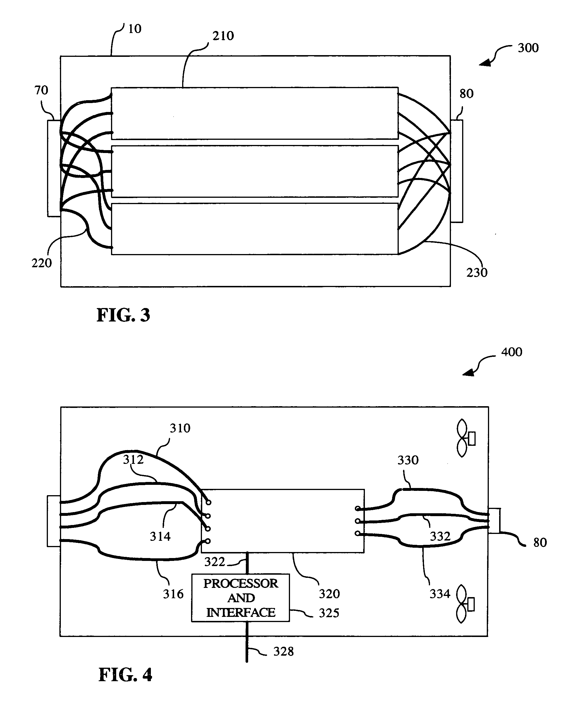
[0029]FIG. 3 shows a universal modular power supply carrier 10 with three po...
embodiment 500
[0032]FIG. 5 illustrates embodiment 500 of mounts for the power supply 410. In FIG. 5, the retaining mounts 450 are L shaped walls secured to the side of the universal modular power supply carrier. The L shaped walls may actually have a right angled Z shape and may be attached to the bottom side 440 by rivets, screws, weld joints, bolts, projecting bolts, attachment clamps formed from part of bottom side 440, or the like. Other variations, such as clamps, are contemplated by the present invention.
[0033]FIGS. 6 and 7 illustrate embodiments 600, 700 of connectors useable with the universal modular power supply carrier 10. As shown in FIG. 6, the connector may have a substantially circular cross section. A protective ring shaped body 510 mechanically mates with a receptacle for carrying the input power and ground levels to the universal modular power supply carrier. The receptacle may be located on a backplane within a computer cabinet or like structure. Pins 520, 530, and 540 may be p...
embodiment 900
[0035] A monitoring circuit, such as a maintenance processor, may be separately housed from the universal modular power supply carrier or may be incorporated, in whole or in part, into the universal modular power supply carrier. FIG. 9 shows an embodiment 900 of a maintenance processor 650 useable in a system with the universal modular power supply carrier. This embodiment is especially useful with a two stage distributed power system where the Ethernet Hub blocks communicate with local translation circuits (e.g., Inter Integrated Bus translation circuits) to the input AC-to-48VDC bulk converters or to AC-to-DC multiple output power supplies. A small power supply driven by a common source of power with the universal modular power supply carrier may power the internal circuitry of the device. The maintenance processor 650 may contain an Ethernet card 690 with a memory 685, a microprocessor 670, and a monitor circuit 675 to measure voltage, current, light, heat, and other conditions i...
PUM
 Abstract
Description
Claims
Application Information
 - R&D Engineer
- R&D Manager
- IP Professional
- Industry Leading Data Capabilities
- Powerful AI technology
- Patent DNA Extraction
Browse by: Latest US Patents, China's latest patents, Technical Efficacy Thesaurus, Application Domain, Technology Topic.
© 2024 PatSnap. All rights reserved.Legal|Privacy policy|Modern Slavery Act Transparency Statement|Sitemap