Backlight unit of liquid crystal display

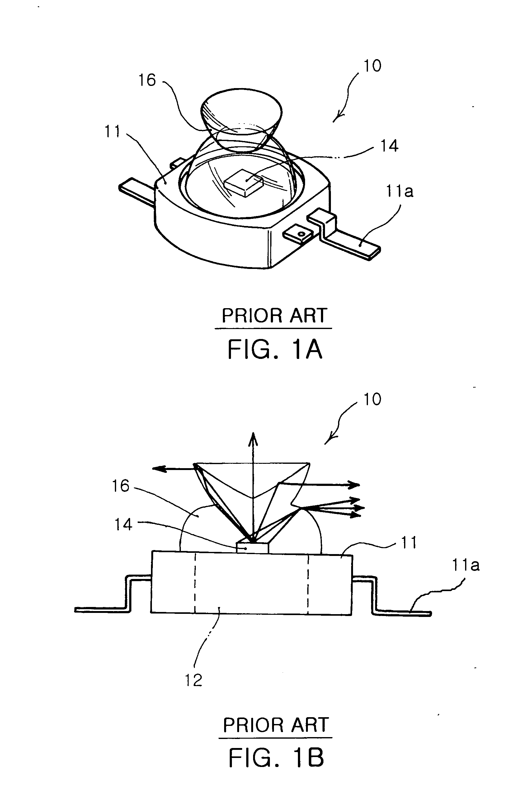
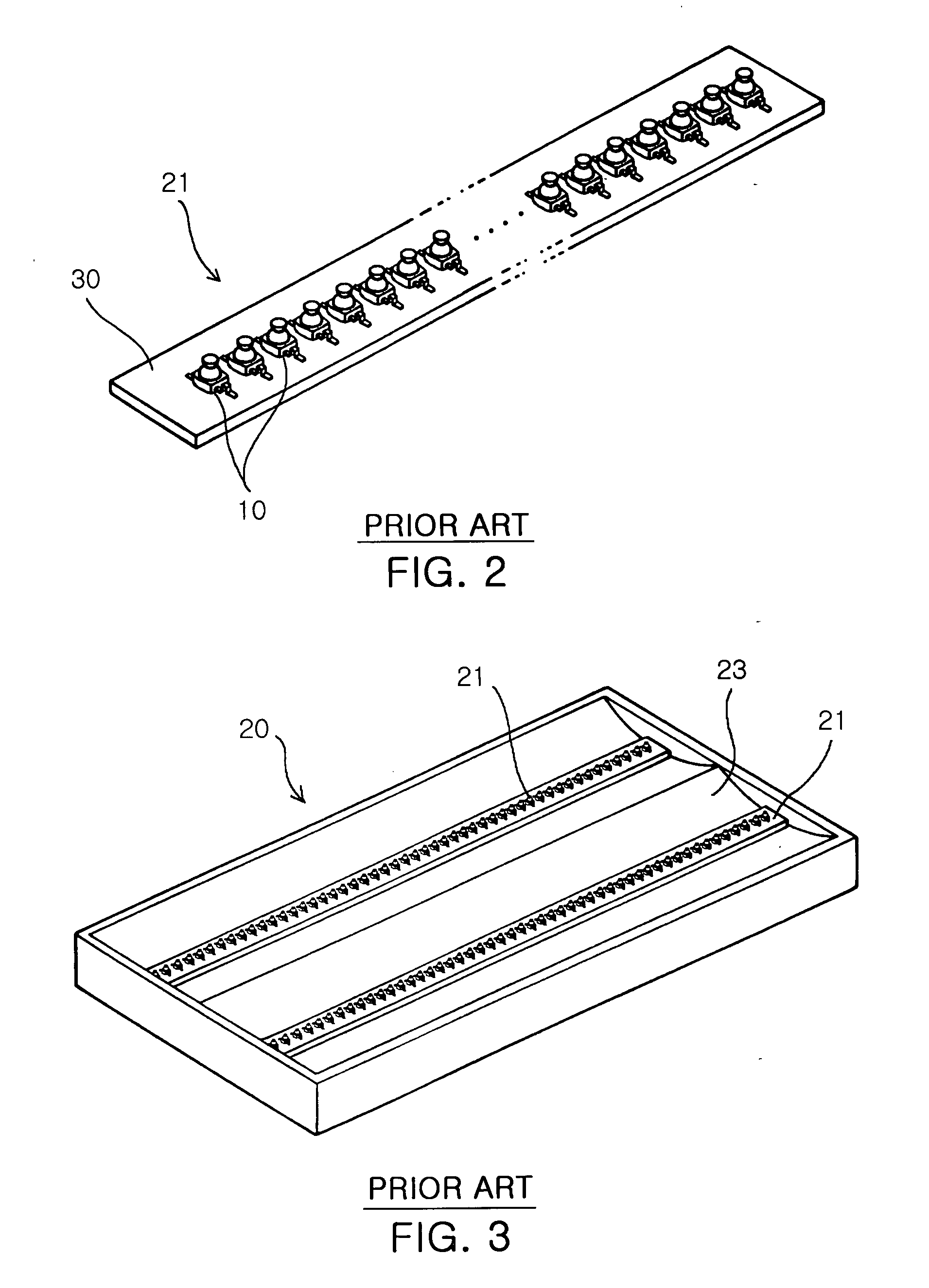
a liquid crystal display and backlight technology, applied in the field of backlight units of liquid crystal displays, can solve the problems of increasing the number of expensive led devices b>10/b> in proportion to the screen size of the lcd display, inefficiency of lcd in view of manufacturing costs, and not being widely applicable to devices b>10/b>

Inactive Publication Date: 2005-12-15
SAMSUNG ELECTRONICS CO LTD
View PDF3 Cites 31 Cited by
  • Summary
  • Abstract
  • Description
  • Claims
  • Application Information

AI Technical Summary

Problems solved by technology

As described above, the conventional backlight unit has problems in that the LED array module 21 and the reflection plate 23 must be redesigned according to the screen size of the LCD display, and in that the number of the expensive LED devices 10 is increased in proportion to the screen size of the LCD display.
Thus, there are problems in that the conventional LCD has inefficiency in view of manufacturing costs, and in that as additional PCBs 21 must be provided according to the screen size of the LCD, the LED devices 10 are not commonly applicable.
Additionally, since the conventional backlight unit adopts a 1-chip per 1-package structure wherein the LED device packages one chip, it is not price competitive.

Method used


Image

  • Backlight unit of liquid crystal display
  • Backlight unit of liquid crystal display
  • Backlight unit of liquid crystal display

Examples


Embodiment Construction

[0032] Now preferred embodiments of the present invention will be described in detail with reference to the accompanying drawings so that those skilled in the art may easily understand and repeat the present invention.

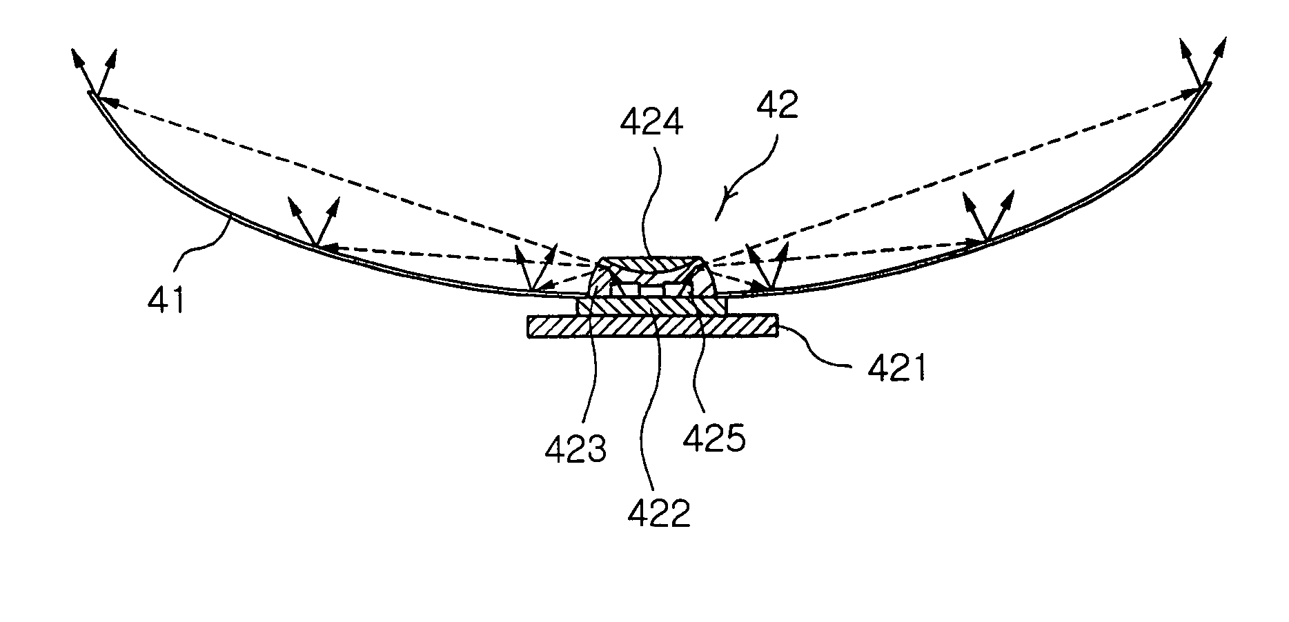
[0033]FIG. 4 is a plain view showing a backlight unit of a liquid crystal display according to the present invention.

[0034] In FIG. 4, reference numeral 41 denotes a unit reflection cell having a cross-sectional area of semi-cylindrical shape and a unit size when a screen of an LCD is equally divided into a predetermined numbers of the unit reflection cells. Reference numeral 42 denotes a light emitting diode package for emitting light in the lateral direction, which integrally packages at least one or more red, blue and green LED chips, and is located at the center of each reflection cell.

[0035] Here, the backlight unit 40 may be achieved by producing a plurality of unit modules, each of which is formed by integrally connecting one light emitting diode package 42 a...


PUM

PropertyMeasurementUnit
distanceaaaaaaaaaa
sizeaaaaaaaaaa
conductiveaaaaaaaaaa

Abstract

Disclosed herein is a backlight unit of a liquid crystal display. The backlight unit comprises a plurality of light emitting diode packages arranged in a matrix while being spaced a uniform distance apart from each other, each light emitting diode package including one or more light emitting diode chips and structured such that light generated from the light emitting chips is emitted in the horizontal direction, and a reflector consisting of a plurality of reflection cells connected to each other in a matrix. Each of the reflection cells of a unit size has each of the light generating packages positioned at the center thereof, and reflects the light, emitted from the light emitting diode at the center thereof in the horizontal direction, to the perpendicular direction.

Description

BACKGROUND OF THE INVENTION [0001] 1. Field of the Invention [0002] The present invention relates to a backlight unit of a liquid crystal display (LCD), and more particularly to a backlight unit of a liquid crystal display, which has a structure commonly applicable to any size of LCDs, and can be structured with a smaller number of light emitting diodes. [0003] 2. Description of the Related Art [0004] A light emitting diode (LED) is a semiconductor light emitting device, which emits various colors of light, with light source being constituted by compound semiconductors made of various materials, such as GaAs, AlGaAs, GaN, InGaN and AlGaInP. With the advent of highly efficient three primary colors (red, blue, green) and white LEDs realized by a nitride having excellent physical and chemical properties, the LEDs have more diverse applications. For instance, the LEDs are used in various applications, such as a backlight of a keypad or a liquid crystal display, a signal lamp, a guide la...

Claims


Application Information

Patent Timeline
Patent Type & Authority Applications(United States)
IPC IPC(8): G02F1/1335G02F1/13357
CPCG02F1/133603Y10S362/80G02F1/133605G02F1/1335
Inventor KIM, HYUNG SUKPARK, YOUNG SAMHAHM, HUN JOOPARK, JUNG KYUJEONG, YOUNG JUNE
Owner SAMSUNG ELECTRONICS CO LTD
Why Eureka
Try Eureka