Physiological sensor combination

a sensor and physiological technology, applied in the field of physiological sensor combination, can solve problems such as brain damage and death

Inactive Publication Date: 2005-12-15
JPMORGAN CHASE BANK NA
View PDF105 Cites 186 Cited by
  • Summary
  • Abstract
  • Description
  • Claims
  • Application Information

AI Technical Summary

Problems solved by technology

Early detection of low blood oxygen level is important in the medical field, for example in critical care and surgical applications, because an insufficient supply of oxygen can result in brain damage and death in a matter of minutes.

Method used


Image

  • Physiological sensor combination
  • Physiological sensor combination
  • Physiological sensor combination

Examples


Embodiment Construction

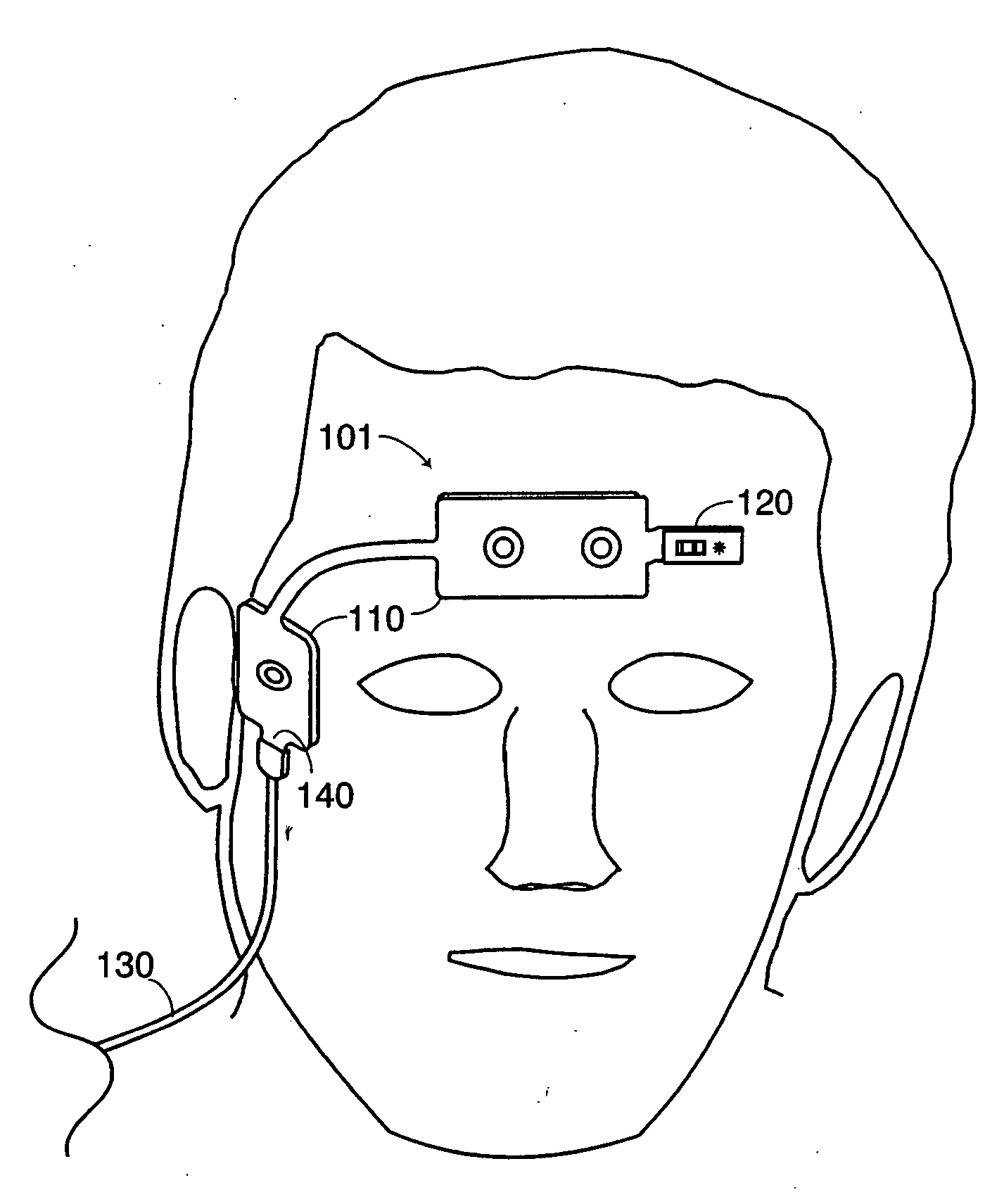
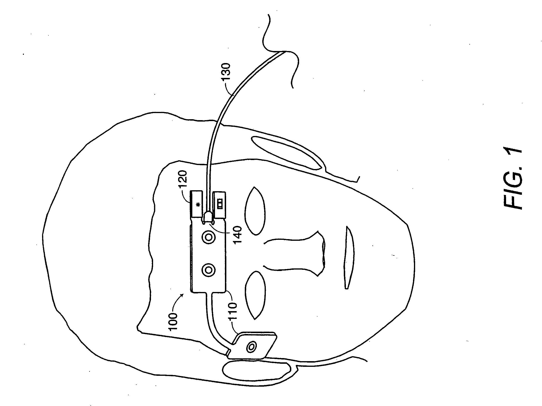
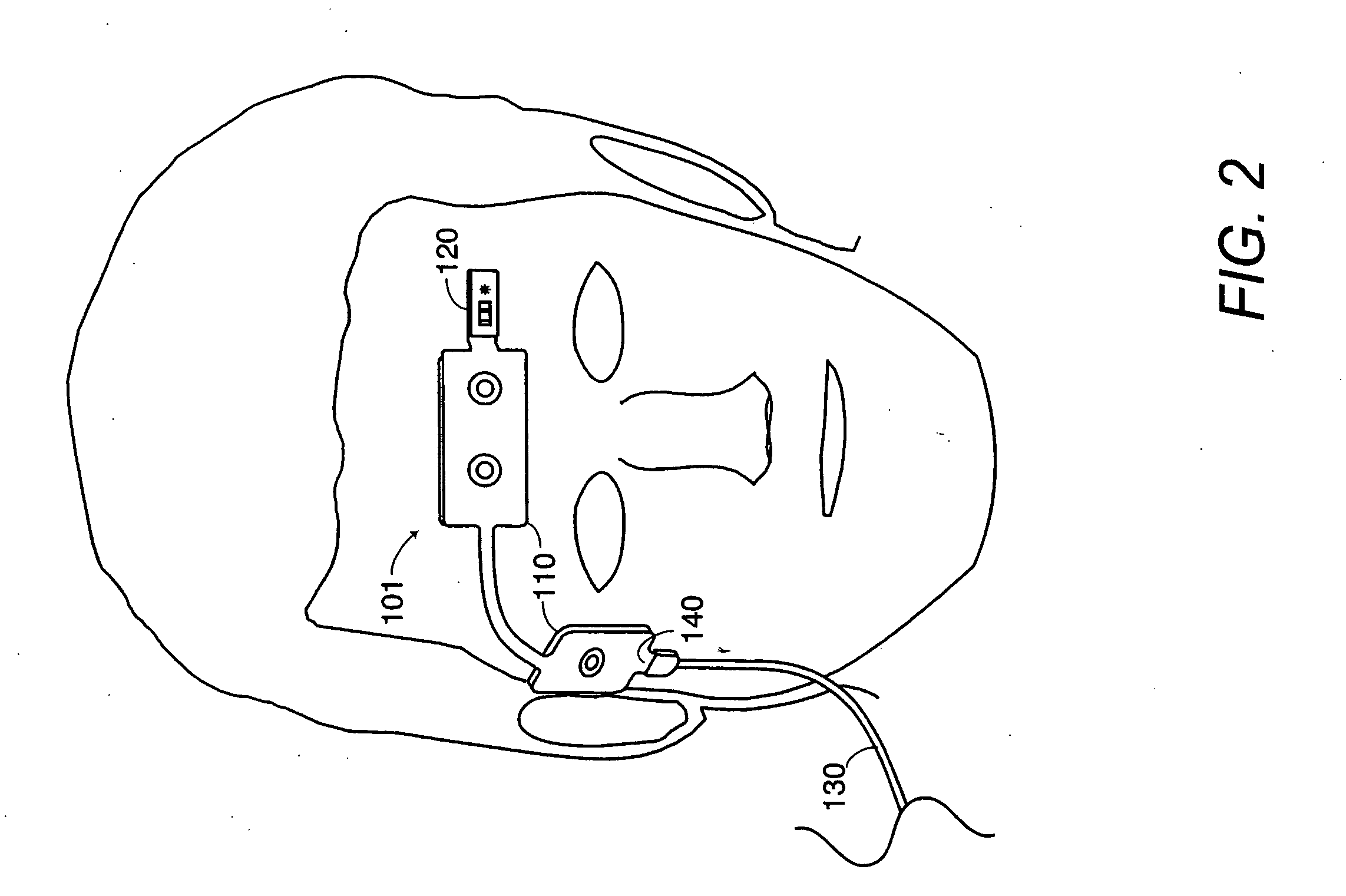
[0015]FIGS. 1-2 show a physiological sensor combination applied to a patient. FIGS. 3-5 illustrate a physiological sensor combination having a biopotential sensor and an optical sensor configured on a single-sided flexible circuit substrate with a shared patient cable connector. FIG. 6 illustrates a physiological sensor combination also having a biopotential sensor and an optical sensor configured on a single-sided flexible circuit substrate. The biopotential sensor and the optical sensor, however, each have separate patient cable connectors. FIG. 7 illustrates a physiological sensor combination having a biopotential sensor and an optical sensor configured on a double-sided circuit substrate, each sensor also having separate patient cable connectors.

[0016]FIGS. 1-2 illustrate a physiological sensor combination applied to the forehead and temple areas of a patient. A patient cable 130 connects the physiological sensor combination 100 (FIG. 1), 101 (FIG. 2) to one or more monitoring ...


PUM


Abstract

A physiological sensor combination has a flexible substrate configured to attach to a tissue site. Multiple sensors are disposed on the substrate, which generate physiological signals. Each of the signals is responsive to a different physiological parameter. Conductors are carried on the substrate and routed between the sensors and at least one connector. The connector is configured to communicate the physiological signals to at least one monitor, which derives measurements of the parameters.

Description

CROSS-REFERENCE TO RELATED APPLICATIONS [0001] This application claims priority benefit under 35 U.S.C. § 120 from, and is a continuation of U.S. patent application Ser. No. 10 / 325,699, filed Dec. 19, 2002, entitled “Physiological Sensor Combination,” now U.S. Pat. No. 6,934,570, which claims priority benefit under 35 U.S.C. § 119(e) from U.S. Provisional Patent Application No. 60 / 347,047, filed Jan. 8, 2002, entitled “Physiological Sensor Combination.” The present application incorporates the foregoing disclosures herein by reference.BACKGROUND OF THE INVENTION [0002] Pulse oximetry is a widely accepted noninvasive procedure for measuring the oxygen saturation level of arterial blood, an indicator of a person's oxygen supply. Early detection of low blood oxygen level is important in the medical field, for example in critical care and surgical applications, because an insufficient supply of oxygen can result in brain damage and death in a matter of minutes. A pulse oximetry system c...

Claims


Application Information

Patent Timeline
Patent Type & Authority Applications(United States)
IPC IPC(8): A61B5/00A61B5/0478
CPCA61B5/0478A61B2562/164A61B5/6814A61B5/14552A61B5/291
Inventor KIANI, MASSI E.AL-ALI, AMMARCOVERSTON, RONALDMASON, GENEROBERTSON, FRED
Owner JPMORGAN CHASE BANK NA
Why Eureka
Try Eureka