Eureka AIR delivers breakthrough ideas for toughest innovation challenges, trusted by R&D personnel around the world.

Basin drainage system for counteracting standing liquid

Inactive Publication Date: 2005-12-22
DECOLAV
View PDF14 Cites 8 Cited by
  • Summary
  • Abstract
  • Description
  • Claims
  • Application Information

AI Technical Summary

Benefits of technology

[0005] The present invention advantageously provides a basin drainage system which overcomes the standing liquid limitations of the prior art and provides a novel and non-obvious drainage system which facilitates the drainage of liquid through the drainage channel of a drain while avoiding standing liquid pools about the drain. A basin drainage system which has been configured in

Problems solved by technology

When standing liquid is allowed to persist within the void of a drainage system, several undesirable conditions can result.
Also, where the liquid is corrosive in nature, the sink can rot in the vicinity of the drain orifice.
In either case, at a minimum, an unattractive discoloration of the sink can develop giving the appearance of generally unsanitary conditions.

Method used


Image

  • Basin drainage system for counteracting standing liquid
  • Basin drainage system for counteracting standing liquid
  • Basin drainage system for counteracting standing liquid

Examples


Embodiment Construction

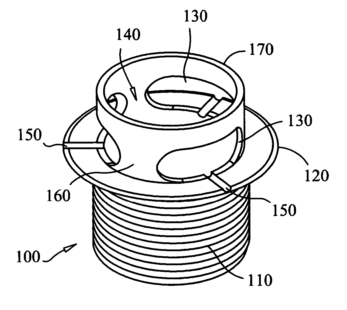
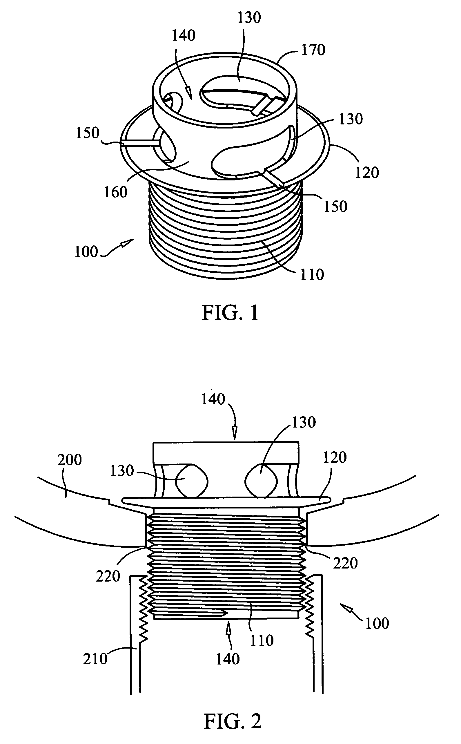
[0014] The present invention is a basin drainage system configured to drain liquid in a basin while avoiding standing water about the orifice of the basin. A basin drainage system which has been configured in accordance with the present invention can include a drain having a drainage channel formed there through for allowing liquid to drain from a top portion of the drain through to a bottom portion of the drain. The drain can include connecting structure such as connecting threads for coupling the bottom portion of the drain to a plumbing system. Additionally, a flange can extend circumferentially from the outer surface of the drain such that the bottom surface of the flange can act as a collar for mating with the perimeter of a basin orifice, for example a sink or tub drain hole.

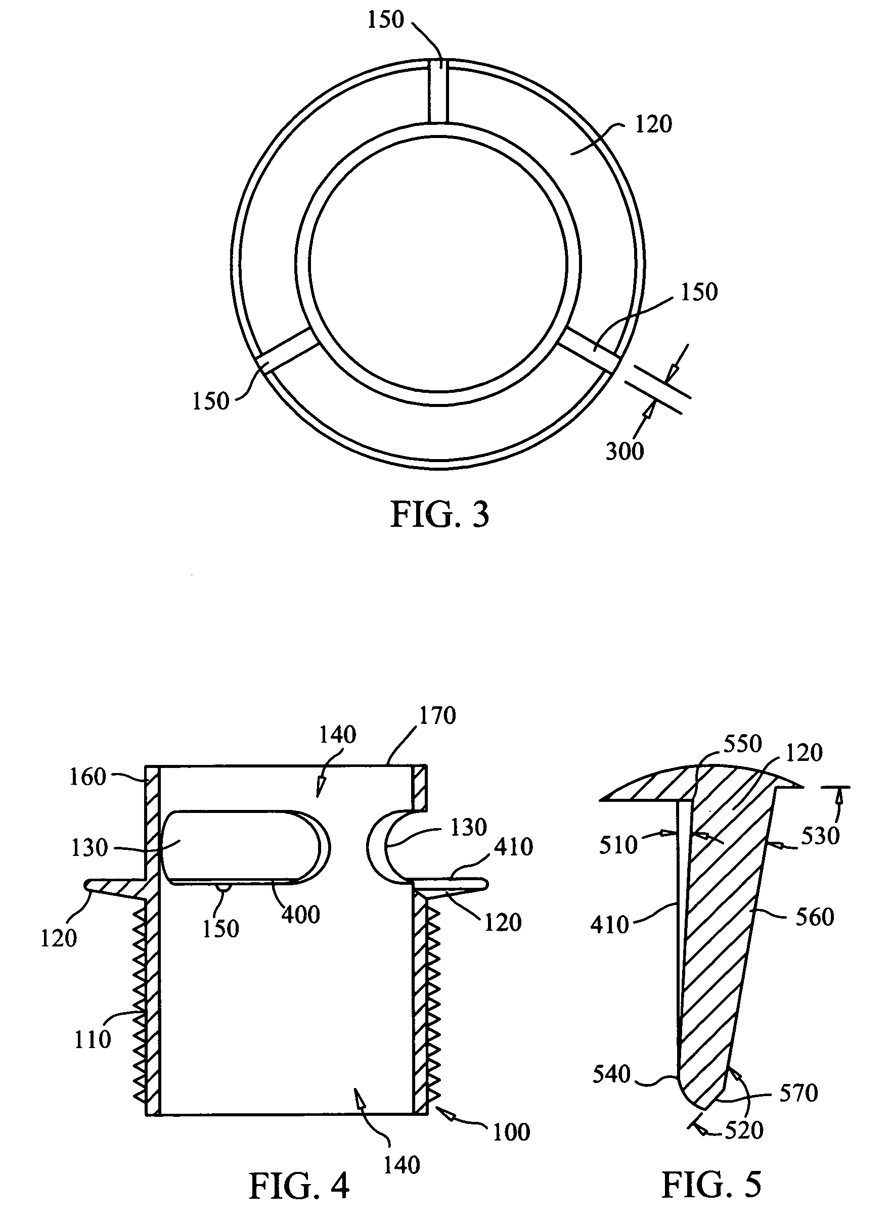
[0015] Importantly, to prevent standing liquid, the top surface of the flange can intersect the exterior portion of the drain at an angle less than ninety degrees. To the extent that the top and bottom su...


PUM


Abstract

A basin drainage system for counteracting standing liquid can include a basin drain having at least one exterior wall defining a drainage channel formed through an interior portion of the basin drain. The system also can include a downwardly sloping flange affixed to the exterior wall of the basin drain. Finally, the system can include axial drainage channels formed in the downwardly sloping flange.

Description

FIELD OF THE INVENTION [0001] The present invention relates to basin hardware and more particularly to basin drainage systems. BACKGROUND OF THE INVENTION [0002] Basin drainage systems enable the draining of liquid from a liquid holding basin, such as a sink or tub, through to a plumbing system such as the centralized plumbing and waste removal systems ordinarily found in residential and commercial structures and shelters. Generally speaking, drainage systems include a drain which can be coupled to an orifice at or near the bottom of the basin. A plumbing system having a drain pipe can be coupled to the bottom of the basin from an opposite end of the orifice. Alternatively, the drain pipe can be coupled directly to an opposing end of the drain. In either case, a drainage port can be formed within the drain through which liquid in the basin can flow into the plumbing system. Notably, most drainage systems include a stopper or drain plug with which the flow through the drainage port c...

Claims


Application Information

Patent Timeline
IPC IPC(8): E03C1/12E03C1/22
CPCE03C1/22
Inventor MAYER, ROBERT H.
Owner DECOLAV
Why Eureka
Eureka Blog
Learn More