Eureka AIR delivers breakthrough ideas for toughest innovation challenges, trusted by R&D personnel around the world.

Electrical connector with drainage channels

Inactive Publication Date: 2011-03-17
HON HAI PRECISION IND CO LTD
View PDF0 Cites 6 Cited by
  • Summary
  • Abstract
  • Description
  • Claims
  • Application Information

AI Technical Summary

Benefits of technology

[0008]In order to achieve the object set forth, an electrical connector has a dielectric housing defining a plurality of passageways and a plurality of contacts disposed in the passageways. Each passageway has a retaining section for retaining the contact. Water drainage channel includes at least one slot below the retaining section and an opening communicating with the slot and the passageways so as to facilitating the drainage of water from an electrical connector.

Problems solved by technology

When the terminal is assembled in the passageway, there isn't enough space to drainage in the passageway.
The water remained in the passageways causes misconnection of the electrical connector.

Method used


Image

  • Electrical connector with drainage channels
  • Electrical connector with drainage channels
  • Electrical connector with drainage channels

Examples


Embodiment Construction

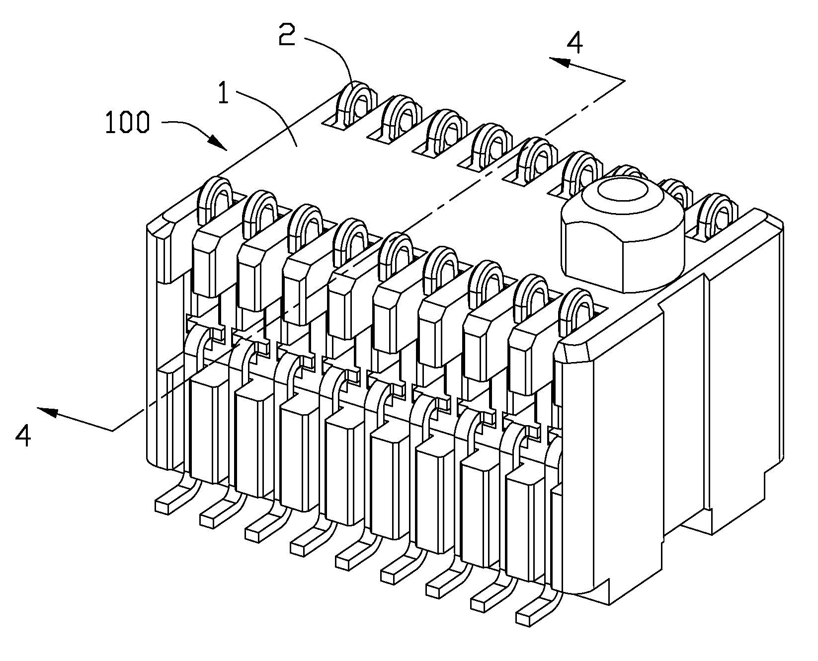
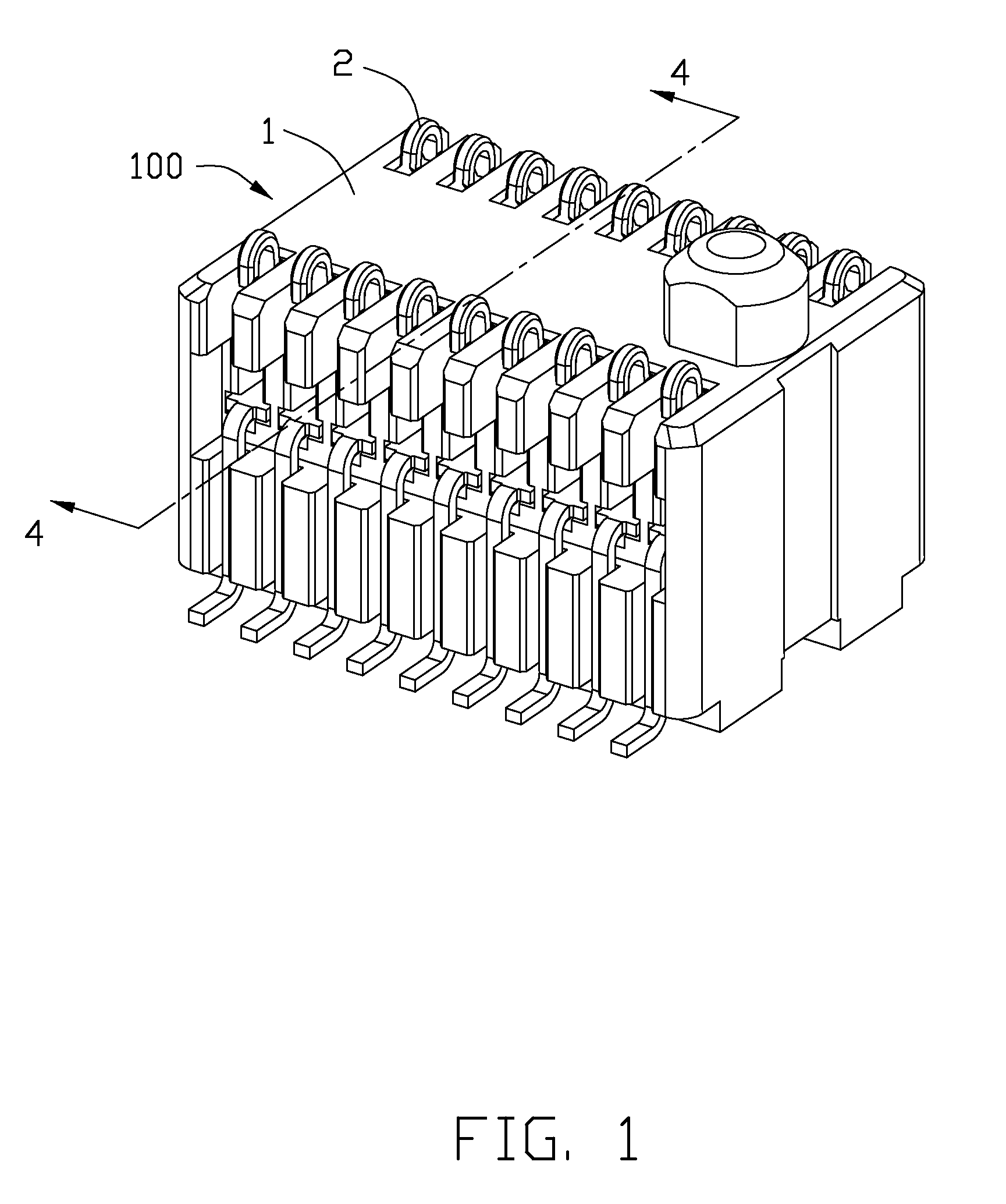
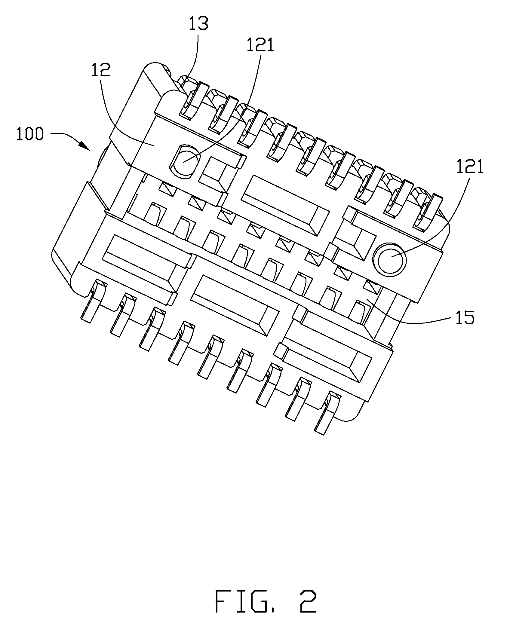
[0014]Reference will now be made in detail to the preferred embodiment of the present invention.

[0015]Referring to FIGS. 1 and 3, an electrical connector 100 for connecting one printed circuit board to another printed circuit board (not shown) in accordance with an embodiment of the present invention comprises a dielectric housing 1 with a number of terminal passageways 14 extending to an exterior in both vertical and horizontal directions, and a plurality of terminals 2 deflectably moving within the terminal passages 14.

[0016]Referring to FIGS. 2-4, the dielectric housing 1 comprises a mating face 11, a board-mounting face 12 opposite to the mating face 11 and two side face 13 connecting with the mating face 11 and a board-mounting face 12. The terminal passageways 14 are arranged at two opposite sides in lengthwise direction and extend through the mating face 11 and the board-mounting face 12 and the side faces 13. Each terminal passageway 14 has a first section 141 adjacent to th...


PUM


Abstract

An electrical connector 100 has a dielectric housing 1 defining a plurality of passageways 14 and a plurality of contacts 2 disposed in the passageways 14. Each passageway 14 has a mounting slot 142 for retaining the contact 2. Water drainage channels include at least one slot 145 below the retaining section 142 and an opening 15 communicating with the slot 145 and the passageways 14 so as to facilitating the drainage of water from an electrical connector 100.

Description

BACKGROUND OF THE INVENTION[0001]1. Field of the Invention[0002]The present invention generally relates to an electrical connector, and more particularly, to a novel structure of a housing for facilitating the drainage of water from an electrical connector.[0003]2. Description of Related Art[0004]Electrical connectors applied to hard disc drive need high sensitivity and cleanliness. Electrical connectors need to be cleaned for better working.[0005]The most board to board electrical connectors in industry are small in size. The electrical connector includes a dielectric housing having a plurality of terminal passageways and a plurality of terminals disposed in the passageways. When the terminal is assembled in the passageway, there isn't enough space to drainage in the passageway. The water remained in the passageways causes misconnection of the electrical connector.[0006]Hence, the present invention is directed to solving this problem in the related art.SUMMARY OF THE INVENTION[0007...

Claims


Application Information

Patent Timeline
IPC IPC(8): H01R4/60
CPCH01R13/2442H01R12/716H01R13/5227
Inventor ZHU, YU
Owner HON HAI PRECISION IND CO LTD
Why Eureka
Eureka Blog
Learn More