Eureka AIR delivers breakthrough ideas for toughest innovation challenges, trusted by R&D personnel around the world.

Pneumatic tire

Pending Publication Date: 2022-01-20
YOKOHAMA RUBBER CO LTD
View PDF0 Cites 0 Cited by
  • Summary
  • Abstract
  • Description
  • Claims
  • Application Information

AI Technical Summary

Benefits of technology

The patent describes a new type of tire with a special design that improves its performance on both dry and wet roads. This is achieved by shaping the tire's sipe chamfer.

Problems solved by technology

However, when a large number of sipes are disposed in a tread portion in order to improve the steering stability performance on wet road surfaces, the rigidity of the ribs decreases, which has the disadvantage that steering stability performance on dry road surfaces deteriorates.
If the sipes are formed and chamfered, edge effects may be lost depending on the shape of the chamfers, and depending on the dimensions of the chamfers, improvement in steering stability performance on dry road surfaces and improvement in steering stability performance on wet road surfaces may be insufficient.

Method used


Image

  • Pneumatic tire
  • Pneumatic tire
  • Pneumatic tire

Examples


examples

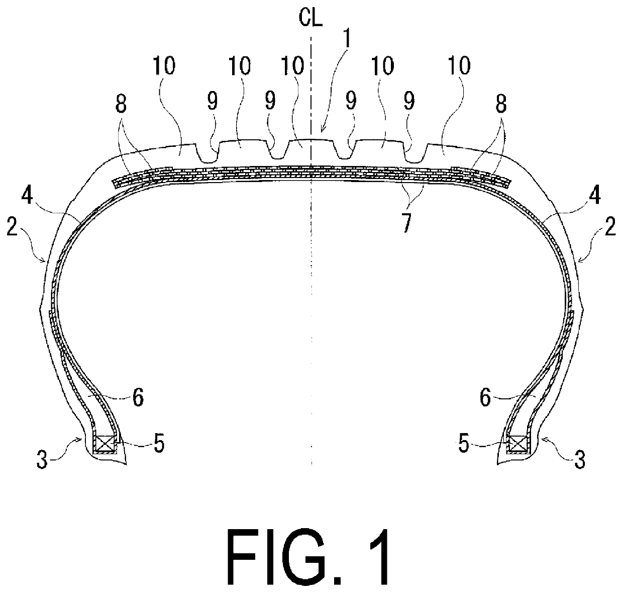
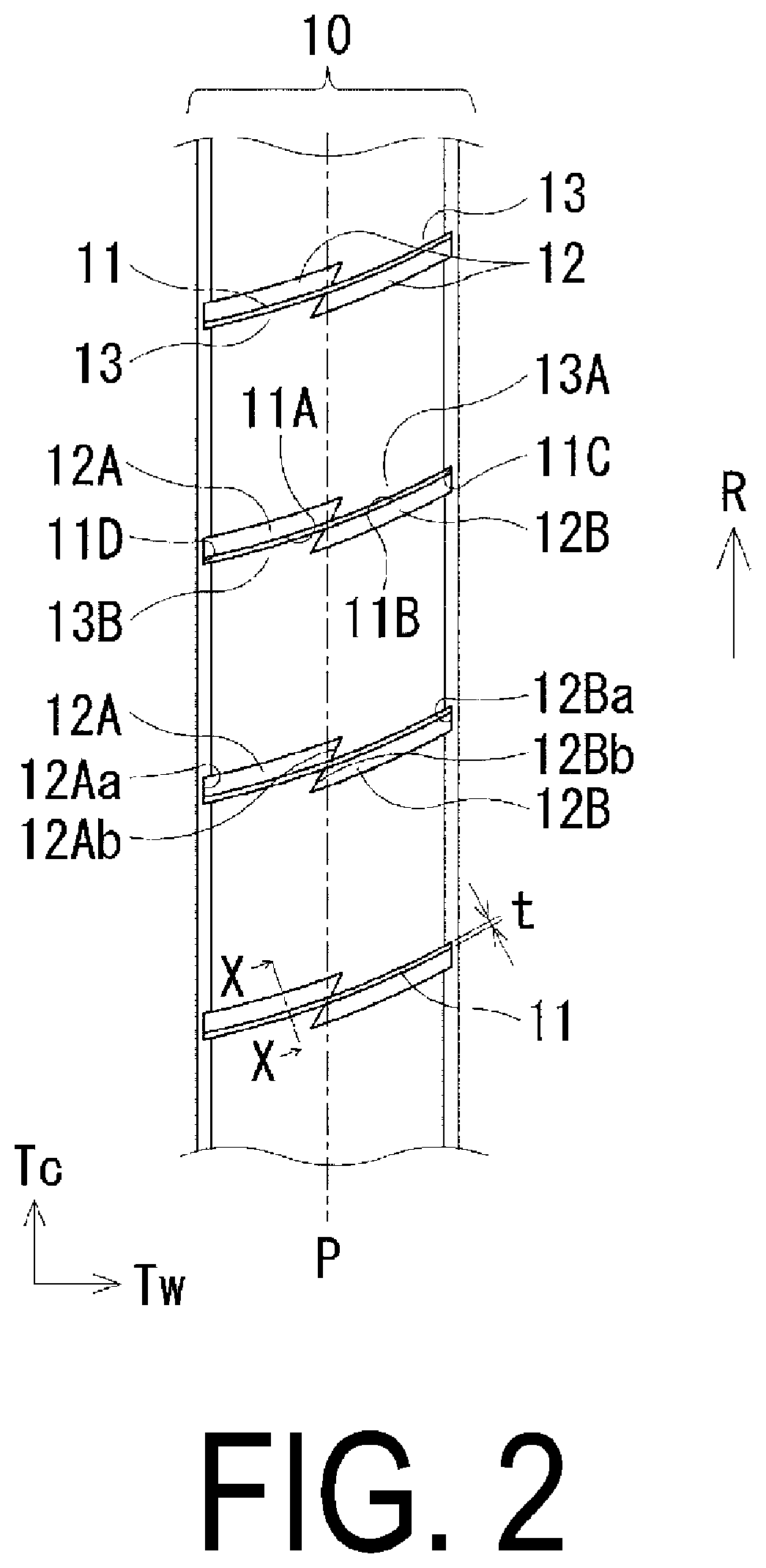
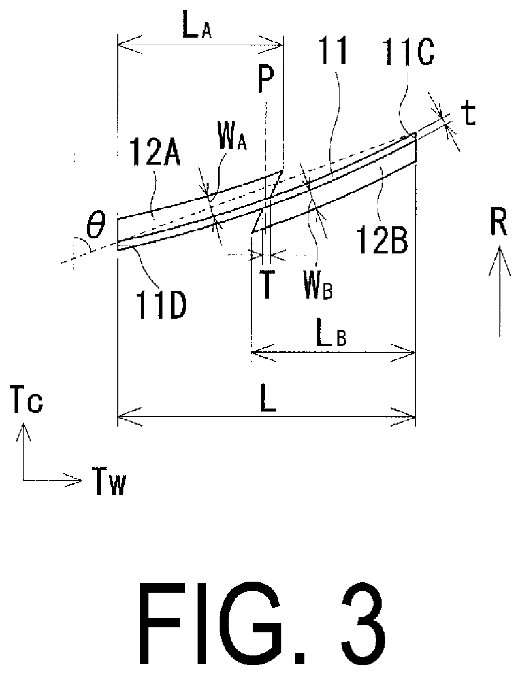
[0046]Tires of Conventional Examples 1 and 2, Comparative Examples 1 and 2, and Examples 1 to 6 are manufactured, in which the pneumatic tire has a tire size of 245 / 40R19 and includes, in a tread portion, a plurality of main grooves extending in the tire circumferential direction, a plurality of rows of ribs defined by the main grooves, and a sipe extending in the tire width direction, the sipe has at least one end communicating with the main groove and a chamfered portion in at least one edge, and the position of the chamfered portion, the arrangement position of the chamfered portion (both sides or one side), a magnitude relationship between the sipe length L and the chamfer length LA, LB, the presence / absence of chamfer at a portion facing the chamfered portion, a magnitude relationship between the radius of curvature TR and the radius of curvature RR, the product of the maximum projection amount D and the maximum width W, the presence / absence of termination of one end of the sip...


PUM


Abstract

Provided is a pneumatic tire. A chamfered portion and a non-chamfered portion are provided in each of an edge on a leading side and an edge on a trailing side of a sipe. In a meridian cross-sectional view, a profile line of a rib projects further to an outer side in a tire radial direction than a reference tread profile line. A radius of curvature TR of the reference tread profile line and a radius of curvature RR of the profile line satisfy a relationship of TR>RR. The chamfered portions on both the leading side and the trailing side are disposed so as to straddle a maximum projection position. A maximum projection amount D of the rib with respect to the reference tread profile line and a maximum width W of the chamfered portion satisfy a relationship of 0.05 mm2<W×D<1.50 mm2.

Description

TECHNICAL FIELD[0001]The present technology relates to a pneumatic tire and particularly relates to a pneumatic tire that can provide improved steering stability performance on dry road surfaces and improved steering stability performance on wet road surfaces in a compatible manner by devising a sipe chamfer shape.BACKGROUND ART[0002]In the related art, in a tread pattern of a pneumatic tire, a plurality of sipes are formed in a rib defined by a plurality of main grooves. By providing such sipes, drainage properties are ensured, and steering stability performance on wet road surfaces is exhibited. However, when a large number of sipes are disposed in a tread portion in order to improve the steering stability performance on wet road surfaces, the rigidity of the ribs decreases, which has the disadvantage that steering stability performance on dry road surfaces deteriorates.[0003]Various pneumatic tires have been proposed in which sipes are formed in a tread pattern and chamfered (for...

Claims


Application Information

Patent Timeline
IPC IPC(8): B60C11/12B60C11/03B60C11/13
CPCB60C11/1281B60C11/0306B60C2011/0386B60C2011/0341B60C11/1392B60C2009/2016B60C2009/2223B60C11/1376
Inventor UEMURA, TAKANORI
Owner YOKOHAMA RUBBER CO LTD
Why Eureka
Eureka Blog
Learn More