Eureka AIR delivers breakthrough ideas for toughest innovation challenges, trusted by R&D personnel around the world.

Grab bar

Active Publication Date: 2008-06-19
WHYZEL ROBERT H J
View PDF21 Cites 7 Cited by
  • Summary
  • Abstract
  • Description
  • Claims
  • Application Information

AI Technical Summary

Benefits of technology

[0012]In accordance with another aspect of the invention, there is provided a method of installing a grab bar on a structure, the method including the steps of fastening the grab bar to the structure such that the grab bar projects from the structure to the projecting side of the grab bar; and sealing the grab bar to the structure. Fastening the grab bar as claimed in claim 1 to the structure may involve fastening the grab bar to the structure at an angle facilitating drainage.

Problems solved by technology

Such grab bars permit items to be stored or hidden from view within the longitudinal bar, and thus are not suitable for use in prisons, juvenile detention facilities, courthouses, jails, hospitals, institutions, mental health units, community homes and other facilities where the storage of certain items is prohibited.
However, such grab bars do not prevent a rope from being placed longitudinally adjacent the longitudinal bar atop or above the underside plate between the longitudinal bar and the wall.
Thus, such grab bars are not fully effective in inhibiting attempts to commit suicide.
However, such endplates do not prevent a rope from being looped around the longitudinal bar itself.
A grab bar with both an underside plate and endplates at both ends of the grab bar suffers from difficulty in draining fluid that accumulates atop the underside plate.
Fluid accumulation can encourage bacterial growth and increase the likelihood of the transmission of infectious diseases, particularly in institutional settings, thereby posing a health risk.
Thus, such grab bars are unsuitable for use wherever a fluid may be present, such as in showers, washrooms and areas where food, drink or waste may spill near the grab bar, including in hospitals and similar institutions.
Providing drainage through a gap between the underside plate and the wall or between the underside plate and the endplates impairs the ability of the grab bar to inhibit the committing of suicide by permitting wire, thin rope or thread to pass through the gap.
The user support member may be enclosed, thereby impeding storage within the user support member.

Method used


Image

  • Grab bar
  • Grab bar
  • Grab bar

Examples


Embodiment Construction

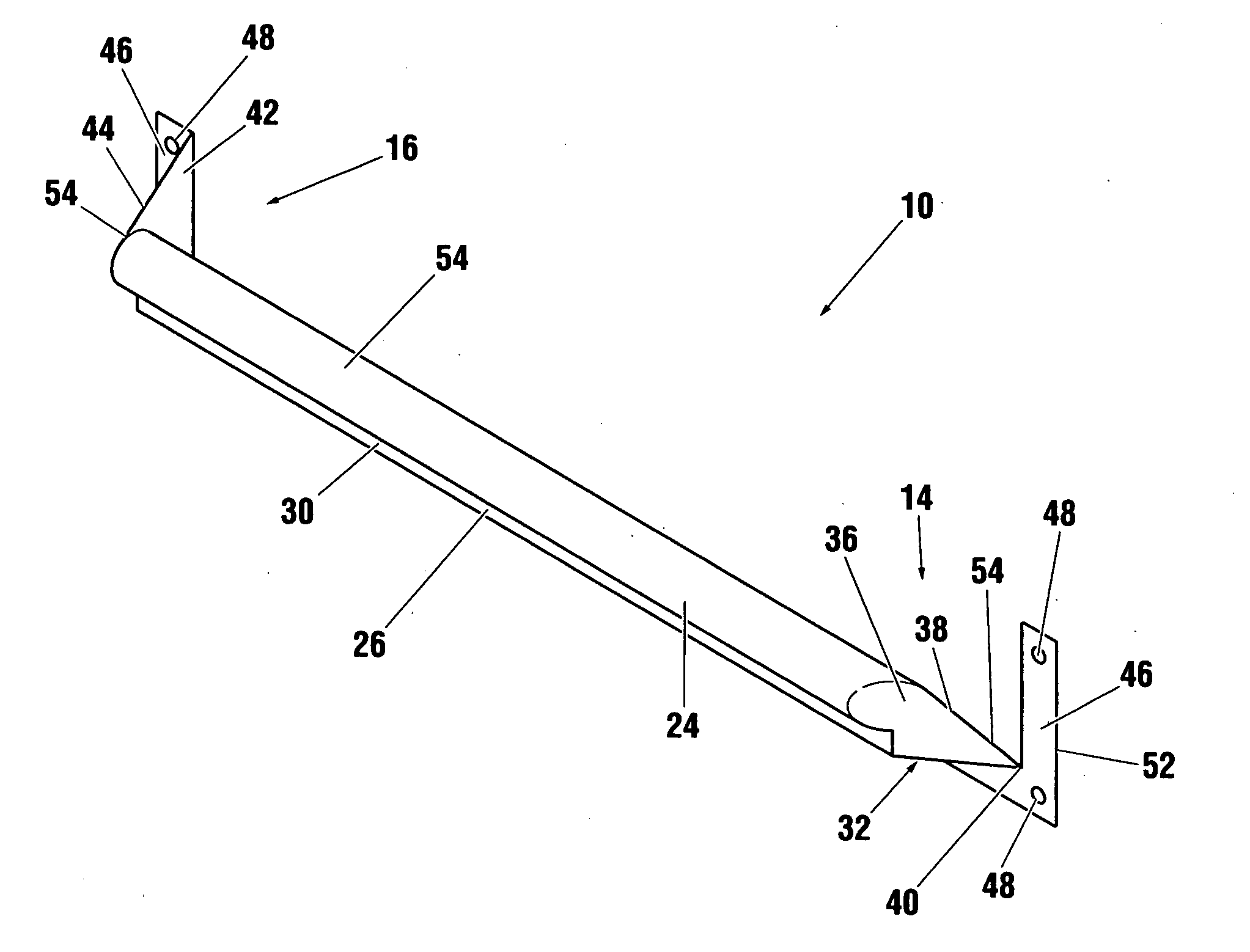
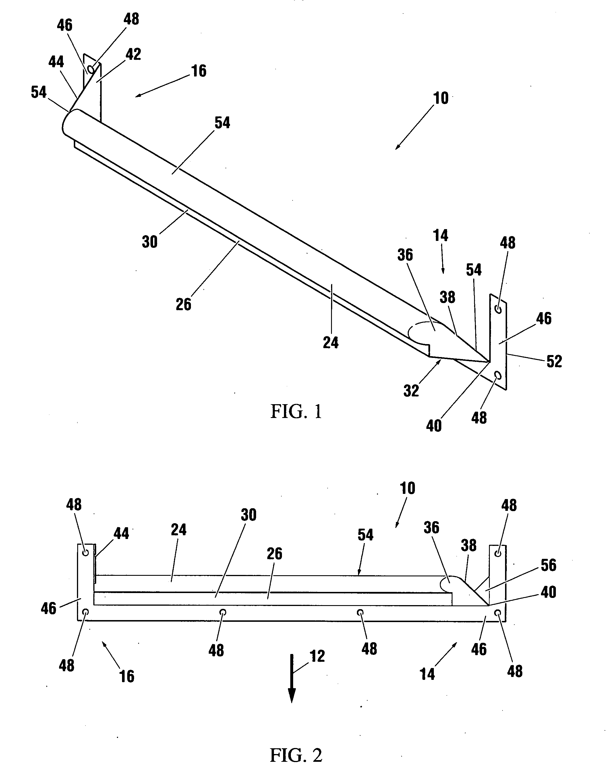
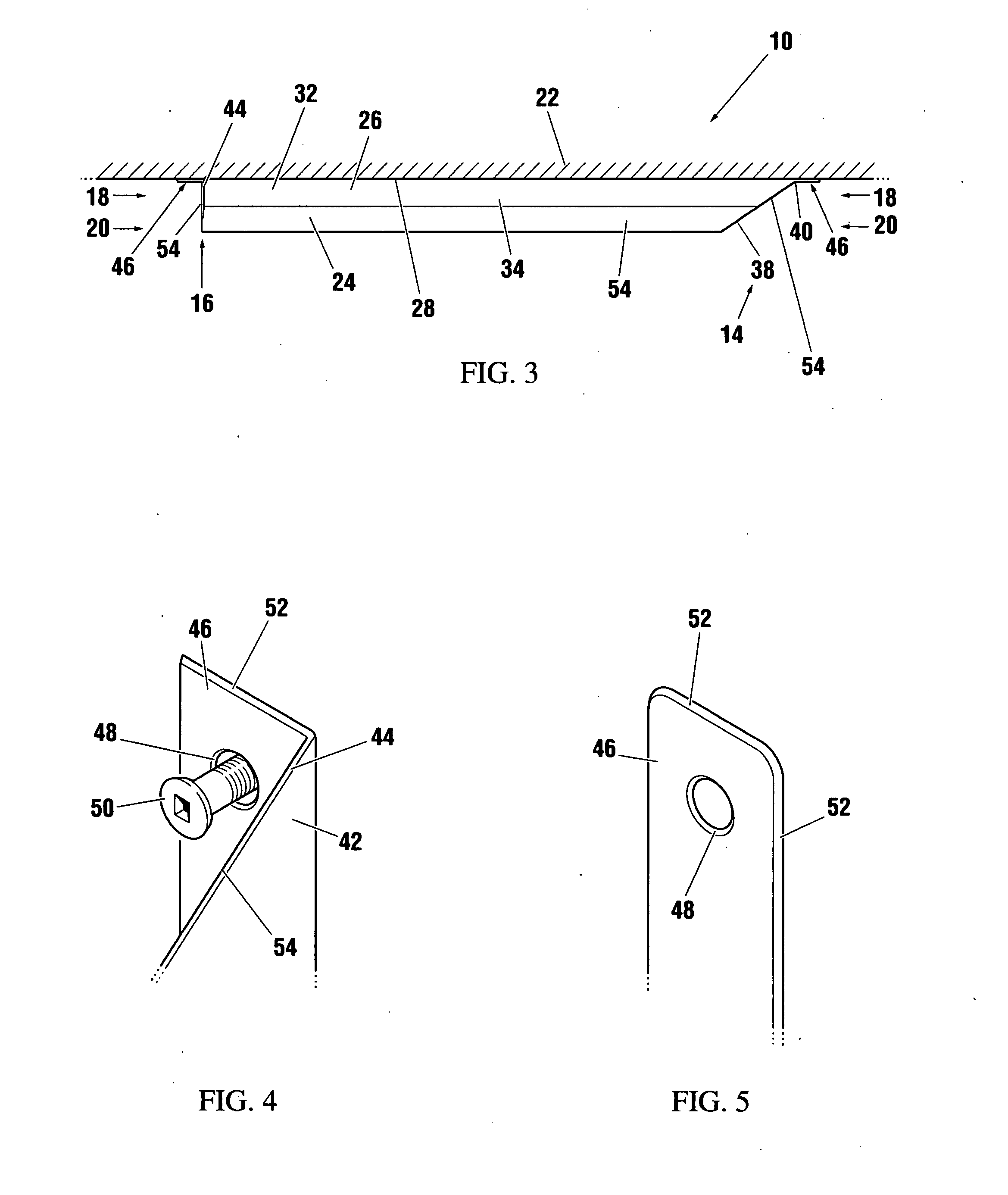
[0026]A grab bar apparatus for projecting from a structure to a projecting side of the grab bar includes: (a) supporting means for supporting a user, the supporting means being disposed at the projecting side of the grab bar; (b) extending means for extending between the projecting side and an attachment side of the grab bar opposite the projecting side, the extending means being attached to the supporting means; (c) draining means for permitting fluid to drain at a first end of the grab bar; and (d) injury inhibiting means for inhibiting injury to the user, the injury inhibiting means being disposed at a second end of the grab bar opposite the first end. The grab bar may further include mounting means for mounting the grab bar to the structure.

[0027]Referring to FIGS. 1 to 3, the grab bar according to a first embodiment of the invention is shown generally at 10. The grab bar 10 provides support to a user, including any or all of assisting a user in standing, sitting, bending, raisi...


PUM


Abstract

A grab bar for projecting from a structure to a projecting side of the grab bar includes a user support member operable to support a user, the user support member being disposed at the projecting side of the grab bar; and an extending member attached to the user support member and dimensioned to extend between the projecting side and an attachment side of the grab bar opposite the projecting side, whereby an upper edge of the grab bar extends from the extending member upwardly and away from the attachment side at a first end of the grab bar and extends upwardly and away from the projecting side at a second end of the grab bar opposite the first end.

Description

BACKGROUND OF THE INVENTION[0001]1. Field of Invention[0002]This invention relates to devices for supporting a user and, in particular, to a grab bar.[0003]2. Description of Related Art[0004]Grab bars mounted to walls conventionally provide a longitudinal bar extending between end sections which mount to the wall. A user may grip the longitudinal bar with their hand for support and assistance in standing and maneuvering. Some grab bars have been designed for compliance with the American Disability Act (ADA).[0005]Some grab bars have longitudinal bars that are not completely enclosed. Such grab bars permit items to be stored or hidden from view within the longitudinal bar, and thus are not suitable for use in prisons, juvenile detention facilities, courthouses, jails, hospitals, institutions, mental health units, community homes and other facilities where the storage of certain items is prohibited.[0006]Some wall mounted grab bars have underside plates extending from the underside of...

Claims


Application Information

Patent Timeline
IPC IPC(8): A47K3/12A47K10/04
CPCA47K17/022Y10T16/498Y10S4/15
Inventor WHYZEL, ROBERT H. J.
Owner WHYZEL ROBERT H J
Why Eureka
Eureka Blog
Learn More