Fluid dispenser

a dispenser and fluid technology, applied in the direction of liquid/fluent solid measurement, container, volume measurement, etc., can solve the problems of actuation, in particular the metering out of the fluid being dispensed, and the small amount of fluid to be expelled, so as to simplify the expulsion of liquid

Inactive Publication Date: 2005-12-22
AIRLESSYST
View PDF6 Cites 36 Cited by
  • Summary
  • Abstract
  • Description
  • Claims
  • Application Information

AI Technical Summary

Benefits of technology

[0005] The present invention therefore proposes resolving the above-mentioned problems by developing a fluid dispenser including a reservoir having deformable walls, and having a volume that is reduced each time the wall is deformed, thereby making fluid dispensing safer and more uniform in terms of the quantities delivered for

Problems solved by technology

Nevertheless, that type of dispenser presents several drawbacks.
Thus, one of the most common problems associated with the use of such a dispenser is that compression that is too great, or that is exerted at an inappropriate location on the reservoir can, for example, cause an incorrect amount of fluid to be expelled, or can, for example, cause a large amount of fluid to be forced towards the bottom of the reservoir, thereby causing only a small amount of fluid to be expelled.
The problem is even more critical when the

Method used


Image

  • Fluid dispenser
  • Fluid dispenser
  • Fluid dispenser

Examples


first embodiment

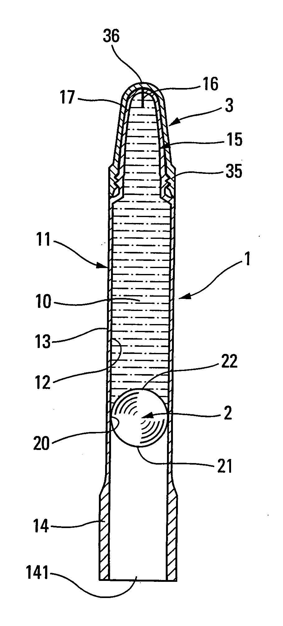
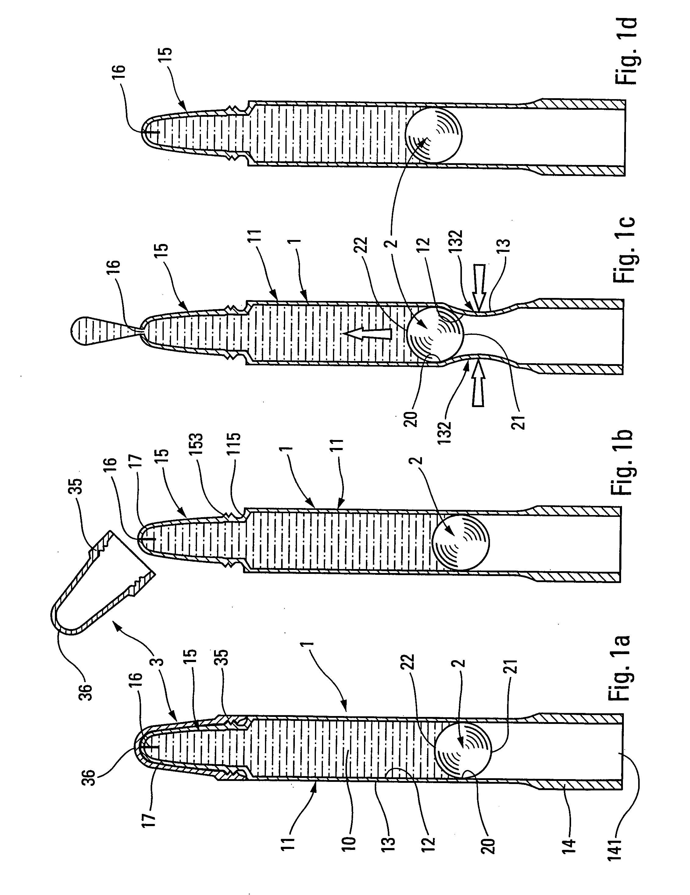
[0042] The second component element of the present invention is the piston element 2; 2′; 2″; or 2′″. The piston element is advantageously made of hard material, e.g. from polypropylene, or from stainless steel. In this case, the piston element is presented in two particular forms that are advantageous. Firstly, the piston element 2 is in the form of a ball, constituting a Secondly, the piston element 2′; 2″; 2′″ is in the form of a cylindrical sleeve 23 surmounted by a plunger 24, constituting other embodiments.

[0043] The ball 2 presents a shape that is advantageously substantially spherical, but it could also present a shape that is oval, ellipsoidal, oblong, . . . . In the invention, the ball is inserted into the body through the opening 141 formed by the sleeve 14. Preferably, the ball is initially engaged as far as the barrel. Thus, the ball, the barrel, and the dispenser head together form a fluid reservoir 10 which is advantageously designed to be filled completely with flui...

second embodiment

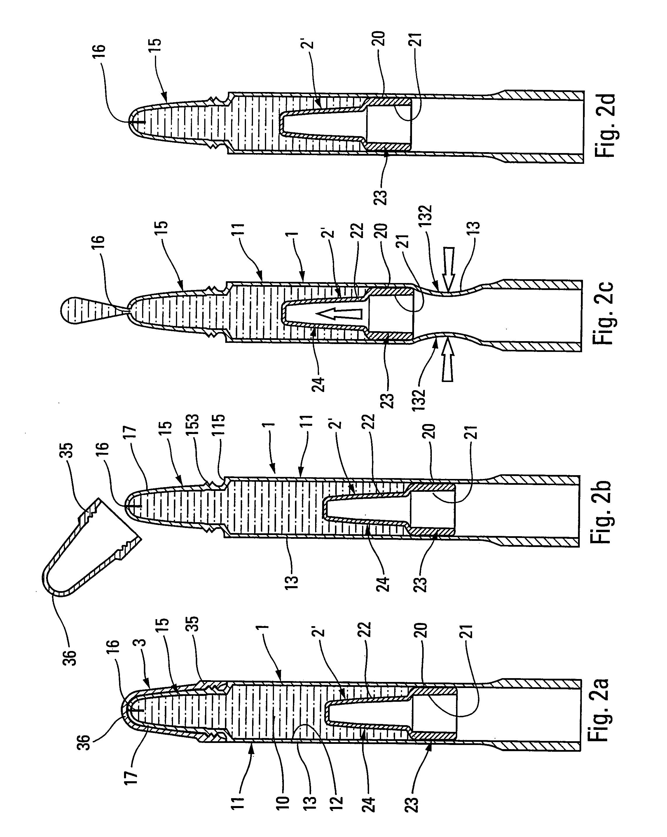
[0045]FIGS. 2a to 2d show the invention in an operating sequence that is identical to the operating sequence shown in FIGS. 1a to 1d; the body is identical, but the ball 2 has been replaced by the piston element 2′. The piston element 2′ comprises a sliding sleeve 23, and a plunger 24. The cylindrical sleeve 23 also presents an outside surface which defines a zone 20 that is in leaktight contact with the inside surface 12 of the barrel. The piston element 2′ also defines a downstream face 22 formed by the outside surface of the plunger, and an upstream face 21 formed by the inside surface of the plunger and of the sleeve. As can be seen in FIG. 2c, the wall 13 of the barrel is likewise deformed by squeezing in an actuator zone 132 situated upstream from the cylindrical sleeve 23. At the actuator zone, the inside surface 12 bears against the upstream face 21 of the cylindrical sleeve, thus causing the piston element 2′ to slide along the barrel. This sliding, and a reduction in the w...


PUM


Abstract

A fluid dispenser comprising a fluid reservoir of variable working volume, at least one deformable wall defining an inside surface, and a dispenser orifice through which the fluid is dispensed while the working volume of the reservoir is being reduced by deforming the deformable wall, the dispenser further comprising a piston element that is in leaktight sliding contact with the inside surface of the deformable wall, said piston element comprising an upstream face that is not in contact with the fluid, and a downstream face that is in contact with the fluid and that forms a displaceable wall of the reservoir, said upstream face being separated from said downstream face by a zone that is in leaktight contact with the inside surface.

Description

[0001] The present invention relates to a fluid dispenser comprising: a fluid reservoir of variable working volume comprising at least one deformable wall defining an inside surface; and a dispenser orifice through which the fluid is dispensed while the working volume of the reservoir is being reduced by deforming the wall. The term “fluid” refers to any substance in liquid, paste, or even powder form, that is suitable for being applied on an application surface, or for being dispensed into the atmosphere. This type of dispenser assembly is used, in particular, in the fields of pharmacy, cosmetics, or even perfumery. BACKGROUND OF THE INVENTION [0002] In the prior art, dispensers having flexible walls that push the fluid towards a dispenser orifice when they are deformed are known. Amongst the most common are tubes having compressible or squeezable walls, more commonly referred to as “squeeze bottles”. That type of dispenser ejects fluid by compressing the wall, and generally presen...

Claims


Application Information

Patent Timeline
IPC IPC(8): B65D1/32B65D83/00
CPCB65D1/32B65D83/0033B65D83/0005
Inventor DECOTTIGNIES, LAURENTBEHAR, ALAIN
Owner AIRLESSYST
Why Eureka
Try Eureka