Plasma generating electrode and plasma reactor

a technology of plasma generating electrodes and plasma reactors, which is applied in the direction of machines/engines, separation processes, discharge tubes luminescnet screens, etc., can solve the problems of plasma generating electrode breakage, etc., to achieve uniform and safe plasma generation, inhibit distortion or breakage of each electrode, and excellent thermal resistance

Inactive Publication Date: 2010-06-01
NGK INSULATORS LTD +1
View PDF15 Cites 2 Cited by
  • Summary
  • Abstract
  • Description
  • Claims
  • Application Information

AI Technical Summary

Benefits of technology

[0021]Since the holding members thus hold electrodes in the state of cantilevers of the different directions alternately at a predetermined interval as a whole, thermal stress is relaxed to effectively inhibit distortion or breakage of each electrode even in the case that the plasma generating electrode is heated at a high temperature or that a local temperature difference is caused by high-temperature exhaust gas discharged from an automobile engine. Further, since a plasma reactor of the present invention is provided with such a plasma generating element, it can generate uniform and safe plasma and is excellent in thermal resistance.

Problems solved by technology

However, there was a problem of deformation or breakage of a plasma generating electrode disposed inside a plasma reactor due to thermal stress in the case of treating exhaust gas having high temperature, such as engine exhaust gas.
In addition, in the case that the electrodes facing each other are made of different materials, stress is caused due to difference in thermal expansion amount of each material to cause a problem of breakage of the plasma generating electrode.

Method used


Image

  • Plasma generating electrode and plasma reactor
  • Plasma generating electrode and plasma reactor
  • Plasma generating electrode and plasma reactor

Examples


example 1

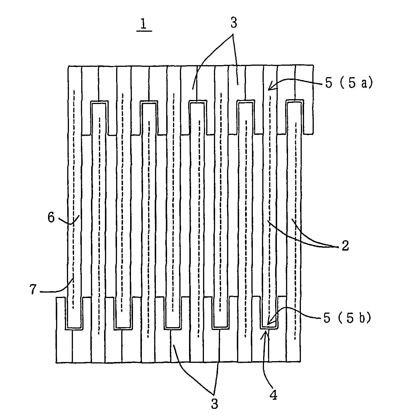
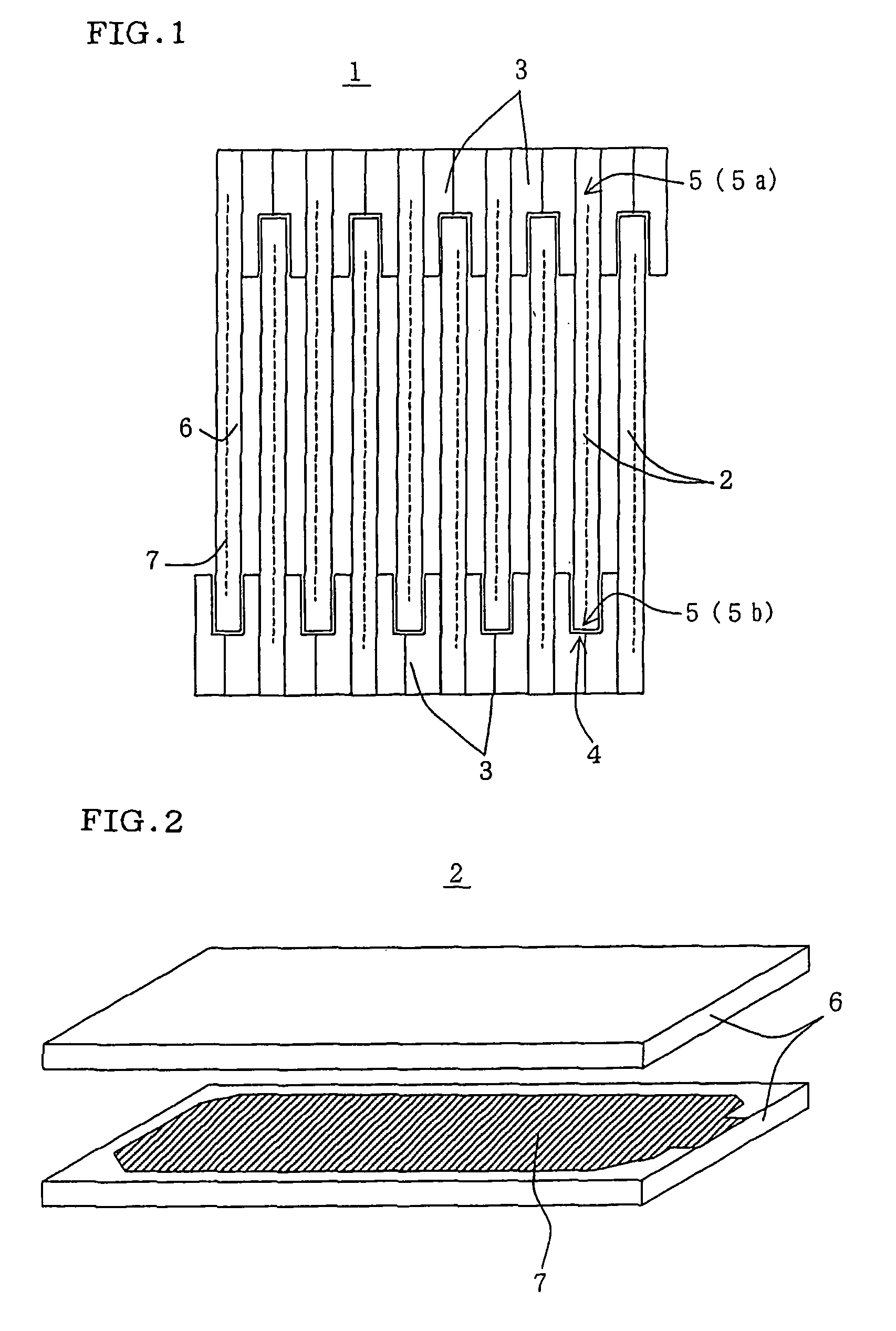
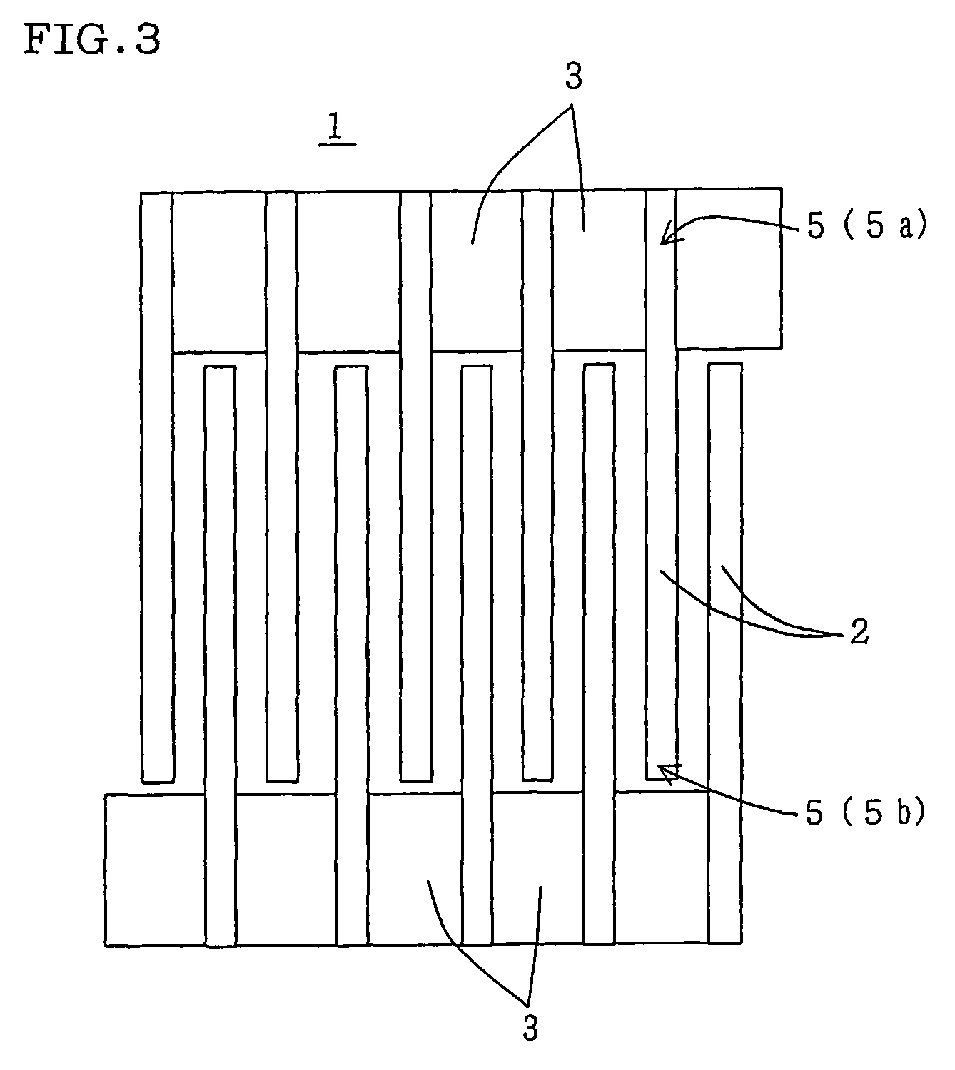
[0092]There was produced a plasma reactor (Example 1) provided with a plasma generating electrode where the electrodes facing each other has a plate-shaped ceramic body serving as a dielectric body and a conductive film disposed inside the ceramic body, and the holding members fix the opposite side end portions (fixed end portions) of the electrodes facing each other in the state of a cantilever in such a condition that the electrodes are held by holding members in the state of cantilevers of the different directions alternately at a predetermined interval as a whole.

[0093]Test gas having a nitrogen monoxide concentration of 200 ppm was sent into the case body constituting the plasma reactor for one hour with changing the gas temperature from room temperature to 600° C. at 10 minute intervals with the maximum space velocity (SV) of 400,000 (l / hr) in the condition that plasma is generated in a plasma generating electrode constituting electrode using a pulse power source having a volt...


PUM


Abstract

A plasma generating electrode 1 of the present invention includes two or more electrodes 2 disposed to face each other, and holding members 3 for holding electrodes 2 at a predetermined interval, and can generate plasma by applying voltage between electrodes 2. At least one of electrodes facing each other 2 has a plate-shaped ceramic body 6 serving as a dielectric body, and a conductive film 7 disposed inside the body 6, and the holding members 3 fix the opposite side end portions 5 (fixed end portions 5a) of electrodes facing each other 2 in the state of a cantilever in such a condition that electrodes 2 are held by holding members in the state of cantilevers of the different directions alternately at a predetermined interval as a whole. This relaxes the thermal stress and effectively prevents distortion and breakage of electrodes caused by to a temperature change.

Description

TECHNICAL FIELD[0001]The present invention relates to a plasma generating electrode and a plasma reactor. More specifically, the present invention relates to a plasma generating electrode and a plasma reactor having relaxed thermal stress and capable of preventing distortion and breakage of the electrode caused by a temperature change.BACKGROUND ART[0002]There have been known that silent discharge is caused by applying a high-voltage alternating current or a periodic pulse voltage on a dielectric body disposed between two electrodes fixed at both end portions to generate a plasma field, where an active species, a radical, and an ion are formed to promote reaction and decomposition of gas and that this can be used for removing harmful components contained in engine exhaust gas or exhaust gas from various kinds of incinerators.[0003]For example, there is disclosed a plasma reactor which treats, e.g., NOx, carbon particulate, HC, and CO contained in engine exhaust gas or exhaust gas fr...

Claims


Application Information

Patent Timeline
Patent Type & Authority Patents(United States)
IPC IPC(8): B01J19/08B01D53/56B01D53/62B01D53/92F01N3/08
CPCB01D53/56B01D53/62B01D53/92B01J19/088F01N3/0892B01J2219/0835B01J2219/0843B01J2219/0875B01J2219/0813
Inventor MIYAIRI, YUKIOFUJIOKA, YASUMASAMASUDA, MASAAKISAKUMA, TAKESHI
Owner NGK INSULATORS LTD
Why Eureka
Try Eureka