Apparatus and method for improving electromagnetic compatibility

Active Publication Date: 2005-12-22
VIAVI SOLUTIONS INC
View PDF3 Cites 40 Cited by
  • Summary
  • Abstract
  • Description
  • Claims
  • Application Information

AI Technical Summary

Benefits of technology

[0006] Accordingly, in a first aspect, the invention provides an apparatus for providing improved electromagnetic compatibility between a power source and a switching element that switches power supplied from the power source to provide a required frequency power supply, the power source and the switching element being coupled via a first power line at a supply potential and a second power line at a reference potential, the apparatus comprising a measuring device for coupling to at least one of the power lines between the power source and the switching element for measuring an electrical variable that fluctuates as the switching element switches power received from the power source, and a signal injector coupled to the measuring device and to at least one of the power lines for injecting a

Problems solved by technology

It will be apparent that whenever a switching element is used to switch power appearing from an input power source, electromagnetic interference is generated that can be conducted back to the power source and cause interference.
This can be particularly disadvantageous at radio frequen

Method used


Image

  • Apparatus and method for improving electromagnetic compatibility
  • Apparatus and method for improving electromagnetic compatibility
  • Apparatus and method for improving electromagnetic compatibility

Examples


Example

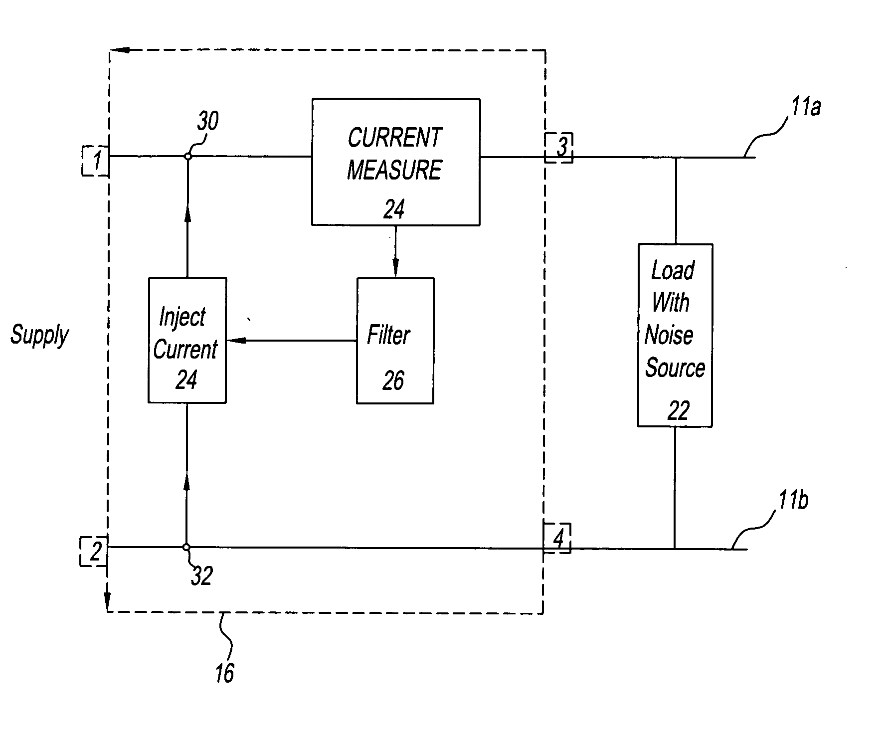
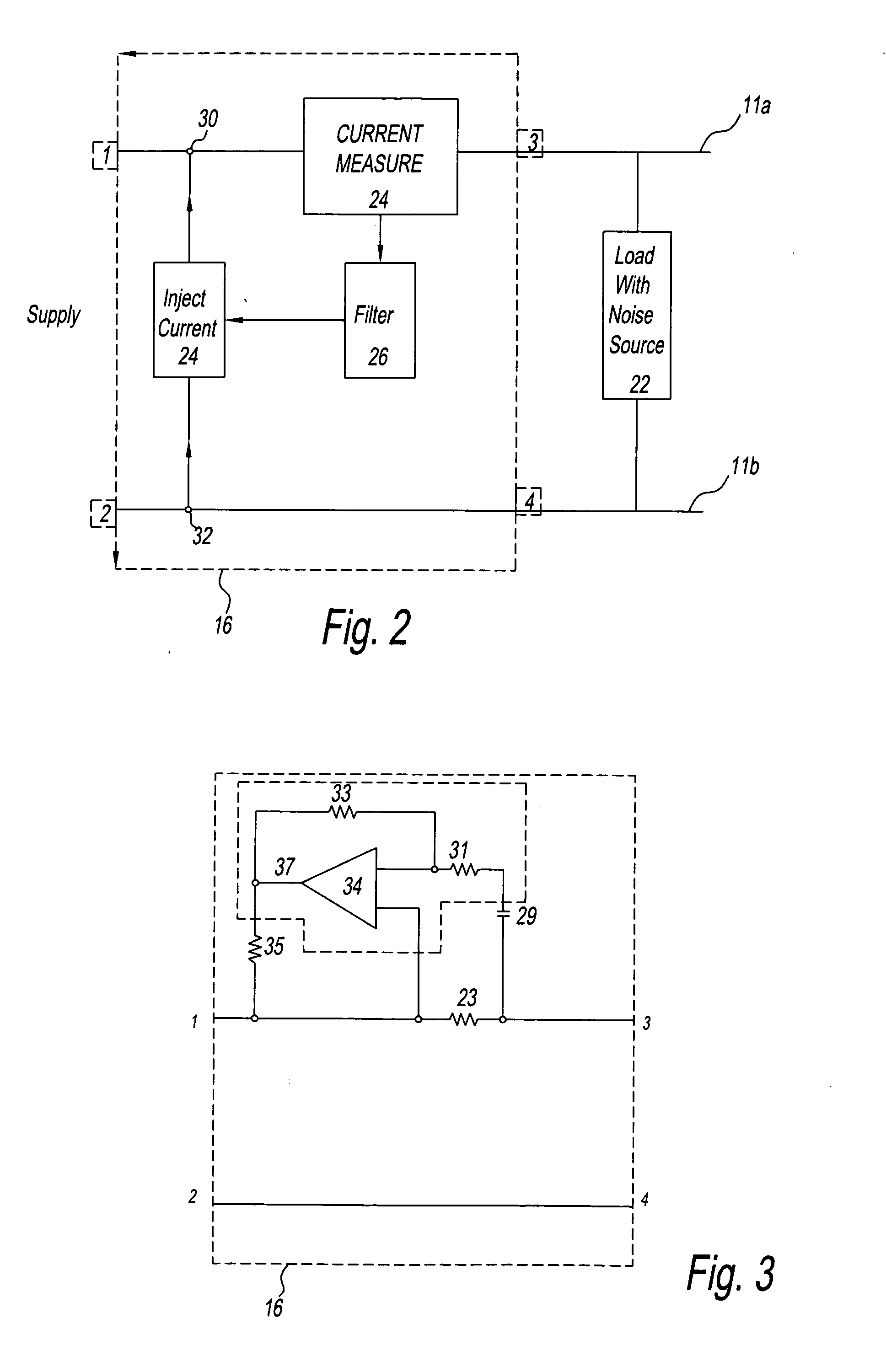
[0033]FIG. 2 shows a schematic block diagram of a first embodiment of the EMC filter 16 of the present invention. This embodiment utilises open loop filtering to try to achieve noise cancellation. The filter 16 of this embodiment is inserted into the apparatus of FIG. 1 as described above. A noise source 22 is shown in FIG. 2 and represents the switching element 19, capacitor 17 and inductors 13 and 15 of FIG. 1, which may generate noise on the first and second power rails 11a, 11b. A measurement device 24 is coupled in series on the first power rail 11a between input 1 and output 3 to monitor the current on the first power rail 11a and produce a measurement parameter proportional to the current flowing on the first power rail 11a. The measurement device 24 has an output coupled to a filter 26, the measurement parameter being passed to the filter 26, where any DC element is substantially blocked from passing through. The filter 26 may also filter the measurement parameter to a level...

Example

[0040]FIG. 4 shows a schematic block diagram of a second embodiment of an EMC filter 116 according to the present invention. This second embodiment utilises closed loop filtering to achieving noise cancellation. Once again, the circuitry forming the EMC filter 116 is inserted into the apparatus 10 of FIG. 1 as described above. Again, a noise source 122 is shown in FIG. 4 and represents the switching element 19, capacitor 17 and inductors 13 and 15 of FIG. 1, which may generate noise on the first and second power rails 11a, 11b. A measurement device 124, coupled in series on the first power rail 111a between input 1 and output 3, monitors the current on the first power rail 111a and produces a measurement parameter proportional to the current flowing on the first power rail 111a. The measurement device 124 has an output coupled to a filter 126, which substantially blocks any DC element passing through. The filter 126 also filters and / or amplifies the measurement parameter to a level ...

Example

[0044]FIG. 6 shows a schematic block diagram of a third embodiment of an EMC filter 216. This third embodiment again utilises closed loop filtering to achieving noise cancellation, although it may be worked in an open loop configuration similar to that of the first embodiment of FIGS. 2 and 3. Again, the circuitry forming the EMC filter 216 is inserted into the apparatus 10 of FIG. 1 as described above. The noise source 222 created by the switching element 19, capacitor 17 and inductors 13 and 15 of FIG. 1 generates noise on the first and second power rails 211a, 211b. A measurement device 224 coupled in parallel between the first power rail 211a and the second power rail 211b monitors the voltage between the first power rail 211a and the second power rail 211b and produces a measurement parameter proportional to that measured voltage. The measurement device 224 has an output coupled to a filter 226, which substantially blocks any DC element passing through. The filter 226 also filt...


PUM


Abstract

A method and apparatus for providing improved electromagnetic compatibility between a power source (20) and a switching element (22) in a switched mode power supply includes a device (24) for measuring an electrical variable, for example current, that fluctuates as the switching element (22) switches power received from the power source (20). A signal injector (28) is arranged to generate an electrical signal, for example current, of substantially the same amplitude, but opposite polarity, as the measured current, and to inject it between the power source (20) and the switching element (22) so as to tend to minimize fluctuations in the electrical variable.

Description

[0001] This invention relates to an apparatus and method for improving electromagnetic compatibility, particularly, though not exclusively, for conducted emissions, especially at lower frequencies. BACKGROUND OF THE INVENTION [0002] Many electronic circuits require pulsed supplies of power and various devices are known that take input power from a power source and provide appropriately pulsed output power. One example of such a device is a switched mode power supply, which utilizes one or more switching elements to generate the pulses that are output at the required frequency. The frequency is dependent on the design of the power supply and can be from approximately 100 kHz to 2 MHz. A duty cycle of the output pulses is dependent on the load of the power supply and the input voltage, and the amplitude of the current pulses can be several times the average input current. [0003] It will be apparent that whenever a switching element is used to switch power appearing from an input power...

Claims


Application Information

Patent Timeline
IPC IPC(8): G05F1/10H02M1/15H03H1/02
CPCH03H1/02H02M1/15
Inventor BRAY, DAVID MICHAEL
Owner VIAVI SOLUTIONS INC
Why Eureka
Try Eureka