Grooved high density plate

a high-density plate, grooved technology, applied in the field of grooved high-density plates, can solve problems such as difficult tasks

Inactive Publication Date: 2005-12-22
APPL BIOSYSTEMS INC
View PDF99 Cites 24 Cited by
  • Summary
  • Abstract
  • Description
  • Claims
  • Application Information

AI Technical Summary

Problems solved by technology

However, the complexity of the human genome and the inter

Method used


Image

  • Grooved high density plate
  • Grooved high density plate
  • Grooved high density plate

Examples


Embodiment Construction

[0196] The following description of various embodiments is merely exemplary in nature and is in no way intended to limit the present teachings, applications, or uses. Although the present teachings will be discussed in some embodiments as relating to polynucleotide amplification, such as PCR, such discussion should not be regarded as limiting the present teaching to only such applications.

[0197] The section headings and sub-headings used herein are for general organizational purposes only and are not to be construed as limiting the subject matter described in any way.

High-Density Sequence Detection System

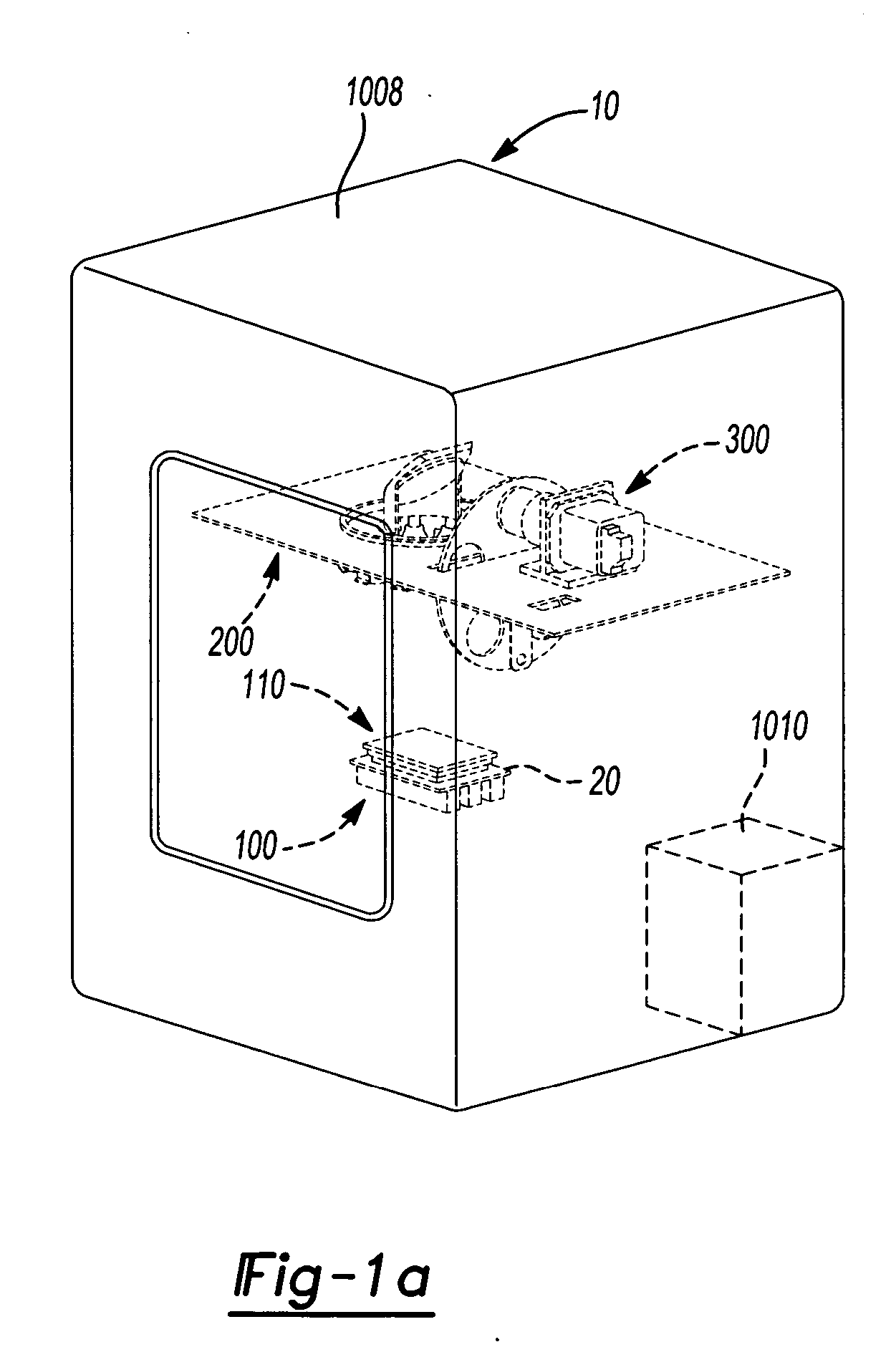
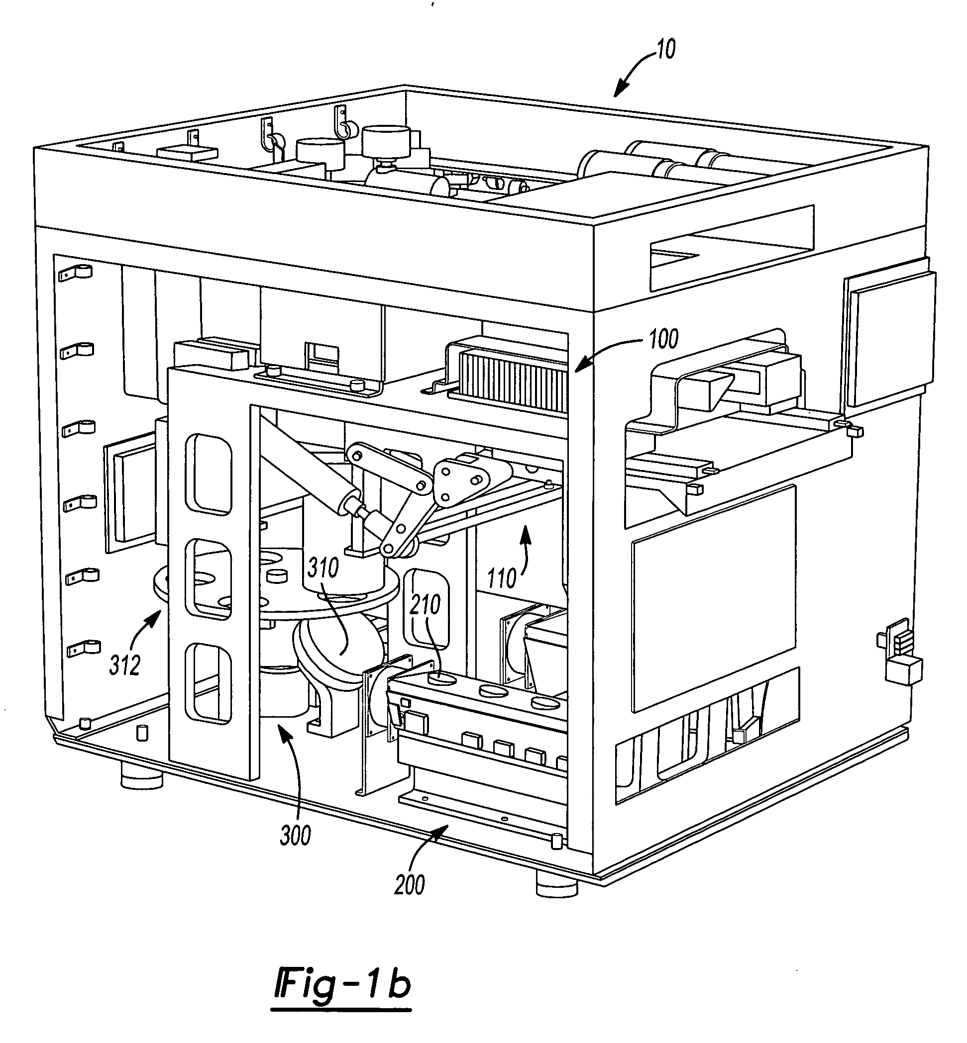
[0198] In some embodiments, a high density sequence detection system comprises one or more components useful in an analytical method or chemical reaction, such as the analysis of biological and other materials containing polynucleotides. Such systems are, in some embodiments, useful in the analysis of assays, as further described below. High density sequence detection systems, in...


PUM

PropertyMeasurementUnit
Lengthaaaaaaaaaa
Lengthaaaaaaaaaa
Electrical conductoraaaaaaaaaa

Abstract

A microplate having a main body portion. The main body portion having a first surface and an opposing second surface, and a groove disposed about the first surface of the main body portion. The groove separates the main body portion into an inboard section and an outboard section. A plurality of wells are formed in the inboard section of the first surface and each of the plurality of wells being sized to receive an assay therein.

Description

CROSS-REFERENCE TO RELATED APPLICATIONS [0001] This application is a continuation-in-part of U.S. patent application Ser. No. 10 / 944,673 filed on Sep. 17, 2004, and U.S. patent application Ser. No. 10 / 944,672 filed on Sep. 17, 2004. U.S. patent application Ser. No. 10 / 944,673 claims a benefit to U.S. Provisional Application No. 60 / 504,500 filed on Sep. 19, 2003; U.S. Provisional Application No. 60 / 504,052 filed on Sep. 19, 2003; U.S. Provisional Application No. 60 / 589,224 filed Jul. 19, 2004; U.S. Provisional Application No. 60 / 589,225 filed on Jul. 19, 2004; and U.S. Provisional Application No. 60 / 601,716 filed on Aug. 13, 2004. U.S. patent application Ser. No. 10 / 944,672 claims the benefit of U.S. Provisional Application No. 60 / 589,224 filed Jul. 19, 2004. [0002] All literature and similar materials cited in this application, including but not limited to, patents, patent applications, articles, books, treatises, and internet web pages, regardless of the format of such literature a...

Claims


Application Information

Patent Timeline
IPC IPC(8): B01L3/00B01L7/00B01L9/00B01L99/00C12M1/34C12P19/34C12Q1/68G01N1/10G01N21/03G01N21/27G01N21/64G01N35/00G01N35/02G01N35/04G01N35/10
CPCB01L3/0293G01N2035/1037B01L3/5027B01L3/502723B01L3/50851B01L3/50853B01L7/52B01L9/50B01L9/523B01L2200/021B01L2200/025B01L2200/0605B01L2200/0642B01L2300/022B01L2300/044B01L2300/046B01L2300/0829B01L2300/0851B01L2300/0864B01L2300/1805B01L2400/0406B01L2400/0409B01L2400/0487G01N21/274G01N21/6452G01N21/648G01N35/028G01N2035/00148G01N2035/00356G01N2035/0405G01N2035/0425B01L3/5025B01L9/56
Inventor SANDELL, DONALD
Owner APPL BIOSYSTEMS INC
Why Eureka
Try Eureka