Fan module

Inactive Publication Date: 2005-12-22
COMP NETWORK TECH
View PDF21 Cites 24 Cited by
  • Summary
  • Abstract
  • Description
  • Claims
  • Application Information

AI Technical Summary

Benefits of technology

[0007] The present invention provides a fan module that easily mounts to the outside of a chassis housing

Problems solved by technology

Electrical circuitry residing in a chassis or housing typically generates heat and therefore requires cooling to perform properly.
It is common for such fans to burn out or require service on a periodic basis during the life of the circuitry in the chassis.
Fan burn out is problematic for at least a couple of reasons.
First, when a fan's performance is compromised, it does not cool the circuitry and therefore the circuitry may overheat and fail.
Second, changing a fan typically requires that the circuitry be shut down while the chassis is opened and the fans replaced.
This is typically slow and detrimental to the operations that rely upon the circuitry.
Still another issue with fans for circuitry has been that it is important t

Method used


Image

  • Fan module
  • Fan module
  • Fan module

Examples


Embodiment Construction

)

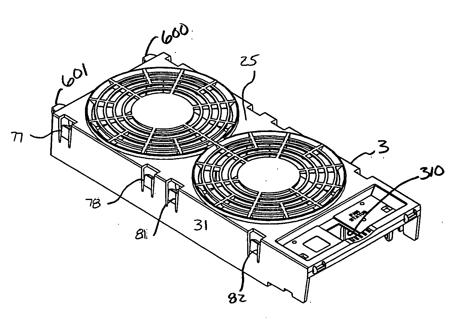
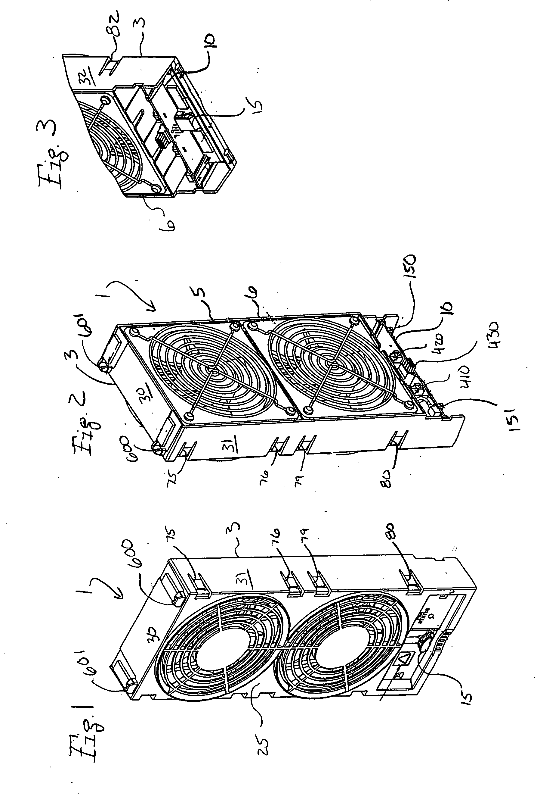
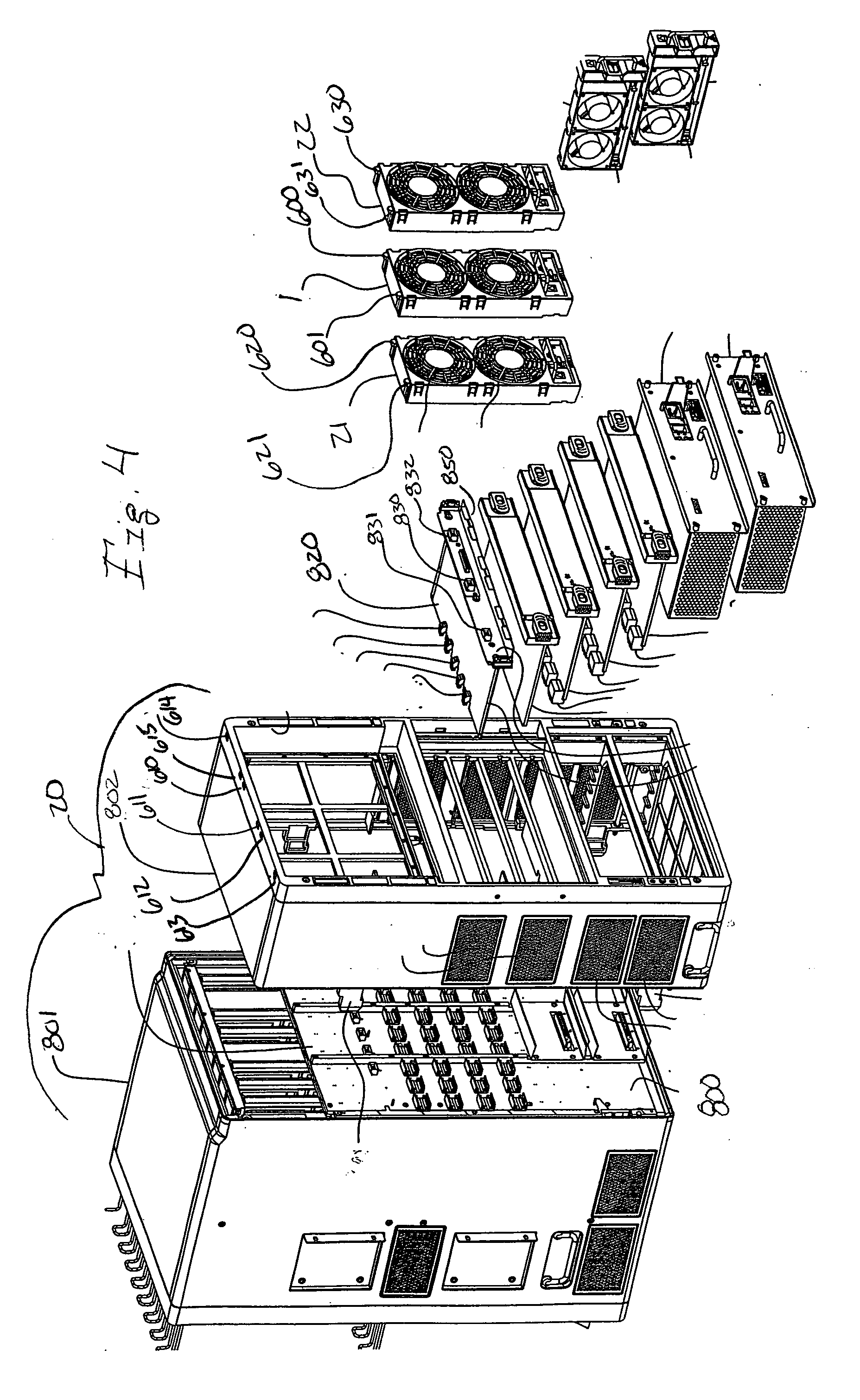
[0035]FIGS. 1 and 2 show a preferred embodiment of a fan module 1. The fan module 1 includes a shell 3 that is molded of plastic as a single unitary body. The shell 3 houses or supports operational components of the fan module 1. These components include individual conventional off-the-shelf fan(s) 5, 6 (more visible in FIG. 2), a printed circuit board assembly 10 (FIG. 2) and a latching member 15 (FIG. 1). As depicted in FIG. 4, the fan module 1 mounts on a chassis 20 that houses electrical circuitry and the fans 5, 6 of the fan module 1 cool the circuitry in the chassis 20. FIG. 4 shows an example of such a chassis 20 with three fan modules 1, 21, 22. The manner in which the fan modules 1, 21, 22 are mounted and secured to a chassis 20 will be discussed below.

[0036] Molded into the shell 3 are various features that allow the operational components of the fan module 1 to be mounted and secured in the shell 3 without any extraneous hardware, providing for relatively quick and chea...


PUM


Abstract

A fan module includes a shell molded from plastic in a unitary construction. In the shell is mounted one or more fans, a printed circuit board assembly and a latching member.

Description

FIELD OF THE INVENTION [0001] The present invention relates generally to a fan module and more particularly to a fan module for snap-in mounting to a chassis for housing electrical circuitry. Further, operational components snap into a shell to form the fan module. BACKGROUND OF THE INVENTION [0002] Electrical circuitry residing in a chassis or housing typically generates heat and therefore requires cooling to perform properly. This cooling is typically accomplished throughfans drawing cooler environmental air through the chassis or exhausting the chassis's internal warm air to the environment. It is common for such fans to burn out or require service on a periodic basis during the life of the circuitry in the chassis. Fan burn out is problematic for at least a couple of reasons. First, when a fan's performance is compromised, it does not cool the circuitry and therefore the circuitry may overheat and fail. Second, changing a fan typically requires that the circuitry be shut down wh...

Claims


Application Information

Patent Timeline
IPC IPC(8): H05K1/00H05K7/20
CPCH05K7/20172
Inventor GOODENOUGH, RYAN K.CARULLO, THOMAS J.
Owner COMP NETWORK TECH
Why Eureka
Try Eureka